Toyota CH-R Service Manual: Rear Door LH ECU Communication Stop (B2324)
DESCRIPTION
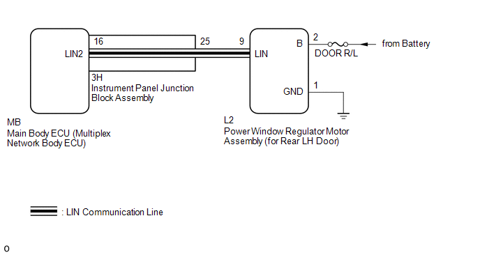
This DTC is stored when LIN communication between the power window regulator motor assembly (for rear LH door) and main body ECU (multiplex network body ECU) stops for 10 seconds or more.
|
DTC No. |
Detection Item |
DTC Detection Condition |
Trouble Area |
|---|---|---|---|
|
B2324 |
Rear Door LH ECU Communication Stop |
No communication between power window regulator motor assembly (for rear LH door) and main body ECU (multiplex network body ECU) for 10 seconds or more. |
|
WIRING DIAGRAM
CAUTION / NOTICE / HINT
NOTICE:
- Inspect the fuses for circuits related to this system before performing the following procedure.
- When a power window regulator motor assembly is replaced or removed
and reinstalled, it is necessary to perform initialization.
Click here
.gif)
- If the main body ECU (multiplex network body ECU) is replaced, refer
to Registration.*1
Click here
- *1: w/ Smart Key System
PROCEDURE
|
1. |
INSPECT INSTRUMENT PANEL JUNCTION BLOCK ASSEMBLY |
(a) Remove the instrument panel junction block assembly.
Click here
|
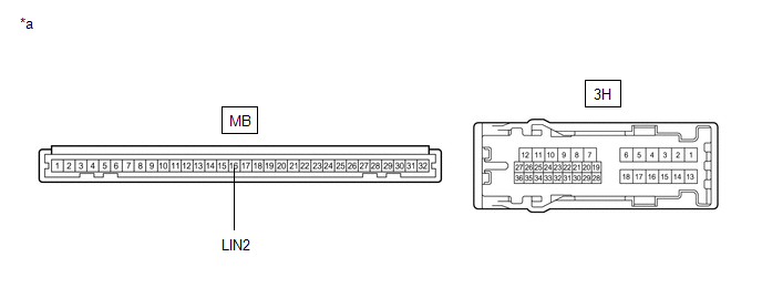
*a |
Component without harness connected (Instrument Panel Junction Block Assembly) |
- |
- |
(b) Remove the main body ECU (multiplex network body ECU) from the instrument panel junction block assembly.
(c) Measure the resistance according to the value(s) in the table below.
HINT:
This inspection is to check the LIN communication line in the instrument panel junction block assembly that connects the wire harness to the built-in main body ECU (multiplex network body ECU).
Standard Resistance:
|
Tester Connection |
Condition |
Specified Condition |
|---|---|---|
|
3H-25 - MB-16 (LIN2) |
Always |
Below 1 Ω |
| NG | .gif) |
REPLACE INSTRUMENT PANEL JUNCTION BLOCK ASSEMBLY
|
|
.gif)
|
2. |
CHECK HARNESS AND CONNECTOR (INSTRUMENT PANEL JUNCTION BLOCK ASSEMBLY - POWER WINDOW REGULATOR MOTOR ASSEMBLY (for Rear LH Door)) |
(a) Disconnect the L2 power window regulator motor assembly (for rear LH door) connector.
(b) Measure the resistance according to the value(s) in the table below.
NOTICE:
Make sure that each ECU is in sleep mode before performing the inspection. To enter sleep mode, turn the ignition switch from ON to off and wait for 180 seconds or more without operating any switches.
Standard Resistance:
|
Tester Connection |
Switch Condition |
Specified Condition |
|---|---|---|
|
3H-25 - L2-9 (LIN) |
Ignition switch off |
Below 1 Ω |
|
L2-9 (LIN) or 3H-25 - Body ground |
Ignition switch off |
10 kΩ or higher |
| NG | |
REPAIR OR REPLACE HARNESS OR CONNECTOR |
|
|
3. |
CHECK HARNESS AND CONNECTOR (POWER WINDOW REGULATOR MOTOR ASSEMBLY (for Rear LH Door) - BATTERY, BODY GROUND) |
(a) Measure the voltage according to the value(s) in the table below.
Standard Voltage:
|
Tester Connection |
Condition |
Specified Condition |
|---|---|---|
|
L2-2 (B) - L2-1 (GND) |
Always |
11 to 14 V |
(b) Measure the resistance according to the value(s) in the table below.
Standard Resistance:
|
Tester Connection |
Condition |
Specified Condition |
|---|---|---|
|
L2-1 (GND) - Body ground |
Always |
Below 1 Ω |
| NG | |
REPAIR OR REPLACE HARNESS OR CONNECTOR |
|
|
4. |
REPLACE POWER WINDOW REGULATOR MOTOR ASSEMBLY (for Rear LH Door) |
(a) Replace the power window regulator motor assembly (for rear LH door).
Click here
|
|
5. |
CHECK FOR DTC |
(a) Clear the DTCs.
Click here
(b) Recheck for DTCs.
Body Electrical > Main Body > Trouble CodesOK:
DTC B2324 is not output.
| OK | |
END (POWER WINDOW REGULATOR MOTOR ASSEMBLY (for Rear LH Door) WAS DEFECTIVE) |
| NG | |
REPLACE MAIN BODY ECU (MULTIPLEX NETWORK BODY ECU)
|
 P/W Master Switch Communication Stop (B1206)
DESCRIPTION
This DTC is stored when LIN communication between the multiplex network master
switch assembly and main body ECU (multiplex network body ECU) stops for 10 seconds
or more.
...
 Lost Communication with Power Source Control (B278C)
DESCRIPTION
This DTC is stored when LIN communication between the certification ECU (smart
key ECU assembly) and power management control ECU stops for 10 seconds or more.
DTC No.
...
Other materials:
Toyota CH-R Service Manual > Meter / Gauge System: Diagnostic Trouble Code Chart
DIAGNOSTIC TROUBLE CODE CHART
Meter / Gauge System
DTC No.
Detection Item
Memory
Link
B1500
Fuel Sender Open Detected
-
B1507
Open in Turn Signal Circuit
DTC store ...
Toyota CH-R Owners Manual > Driving procedures: Engine (ignition) switch (vehicles with a smart key system)
Performing the following operations when carrying the electronic
key on your person starts the engine or changes engine switch modes.
Starting the engine
Check that the parking brake is set.
Check that the shift lever is in P.
Firmly depress the brake pedal.
and
message will be displ ...
Toyota C-HR (AX20) 2023-2026 Owner's Manual
Toyota CH-R Owners Manual
- For safety and security
- Instrument cluster
- Operation of each component
- Driving
- Interior features
- Maintenance and care
- When trouble arises
- Vehicle specifications
- For owners
Toyota CH-R Service Manual
- Introduction
- Maintenance
- Audio / Video
- Cellular Communication
- Navigation / Multi Info Display
- Park Assist / Monitoring
- Brake (front)
- Brake (rear)
- Brake Control / Dynamic Control Systems
- Brake System (other)
- Parking Brake
- Axle And Differential
- Drive Shaft / Propeller Shaft
- K114 Cvt
- 3zr-fae Battery / Charging
- Networking
- Power Distribution
- Power Assist Systems
- Steering Column
- Steering Gear / Linkage
- Alignment / Handling Diagnosis
- Front Suspension
- Rear Suspension
- Tire / Wheel
- Tire Pressure Monitoring
- Door / Hatch
- Exterior Panels / Trim
- Horn
- Lighting (ext)
- Mirror (ext)
- Window / Glass
- Wiper / Washer
- Door Lock
- Heating / Air Conditioning
- Interior Panels / Trim
- Lighting (int)
- Meter / Gauge / Display
- Mirror (int)
- Power Outlets (int)
- Pre-collision
- Seat
- Seat Belt
- Supplemental Restraint Systems
- Theft Deterrent / Keyless Entry

0.0825