Toyota CH-R Service Manual: Seat Heater Control
Components
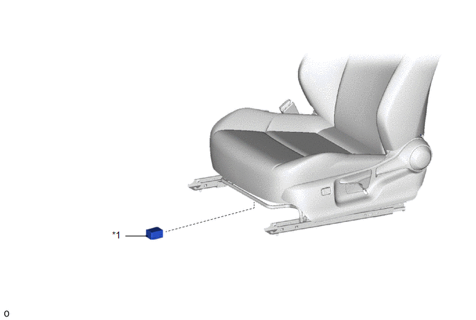
COMPONENTS
ILLUSTRATION
|
*1 |
SEAT HEATER CONTROL SUB-ASSEMBLY |
- |
- |
Removal
REMOVAL
CAUTION / NOTICE / HINT
The necessary procedures (adjustment, calibration, initialization, or registration) that must be performed after parts are removed, installed, or replaced during the seat heater control sub-assembly removal/installation are shown below.
Necessary Procedure After Parts Removed/Installed/Replaced|
Replacement Part or Procedure |
Necessary Procedure |
Effect/Inoperative when not Performed |
Link |
|---|---|---|---|
|
Disconnect cable from negative battery terminal |
Initialize back door lock |
Power door lock control system |
|
|
Memorize steering angle neutral point |
Lane departure alert system (w/ Steering Control) |
|
|
|
Pre-collision system |
CAUTION:
- Be sure to read Precaution thoroughly before servicing.
.png)
Click here
.gif)
- Wear protective gloves. Sharp areas on the parts may injure your hands.
HINT:
- Use the same procedure for the driver side and front passenger side.
- The procedure listed below is for the driver side.
PROCEDURE
1. REMOVE FRONT SEAT ASSEMBLY
Click here
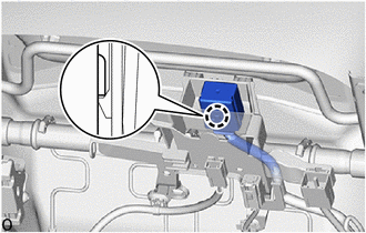
2. REMOVE SEAT HEATER CONTROL SUB-ASSEMBLY
|
(a) Disengage the claw to separate the seat heater control sub-assembly. |
|
|
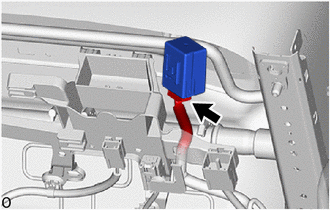
(b) Disconnect the connector to remove the seat heater control sub-assembly. |
|
Installation
INSTALLATION
CAUTION / NOTICE / HINT
CAUTION:
- Be sure to read Precaution thoroughly before servicing.
.png)
Click here
.gif)
- Wear protective gloves. Sharp areas on the parts may injure your hands.
HINT:
- Use the same procedure for the driver side and front passenger side.
- The procedure listed below is for the driver side.
PROCEDURE
1. INSTALL SEAT HEATER CONTROL SUB-ASSEMBLY
(a) Connect the connector.
|
(b) Engage the claw to install the seat heater control sub-assembly. |
|
.png)
2. INSTALL FRONT SEAT ASSEMBLY
Click here
 Reassembly
REASSEMBLY
CAUTION / NOTICE / HINT
CAUTION:
Wear protective gloves. Sharp areas on the parts may injure your hands.
PROCEDURE
1. INSTALL BENCH TYPE REAR SEAT CUSHION COVER
NOTICE:
When installi ...

Other materials:
Toyota CH-R Owners Manual > Operating the lights and wipers: Rear window wiper and washer
Operating instructions
Turning the
switch
turns on the rear window wiper and washer as follows:
OFF *1 or
*2
Off
INT *1 or
*2
Intermittent window wiper operation
ON *1 or
*2
Normal window wiper operation
*1: For U.S.A.
*2: For Canada
Washer/wiper dual operation ...
Toyota CH-R Service Manual > Rear Airbag Sensor: On-vehicle Inspection
ON-VEHICLE INSPECTION
CAUTION / NOTICE / HINT
CAUTION:
Be sure to correctly follow the removal and installation procedures for the No.
2 side airbag sensors.
PROCEDURE
1. INSPECT NO. 2 SIDE AIRBAG SENSOR (for Vehicle not Involved in Collision)
(a) Perform a diagnostic system check.
Click he ...
Toyota C-HR (AX20) 2023-2026 Owner's Manual
Toyota CH-R Owners Manual
- For safety and security
- Instrument cluster
- Operation of each component
- Driving
- Interior features
- Maintenance and care
- When trouble arises
- Vehicle specifications
- For owners
Toyota CH-R Service Manual
- Introduction
- Maintenance
- Audio / Video
- Cellular Communication
- Navigation / Multi Info Display
- Park Assist / Monitoring
- Brake (front)
- Brake (rear)
- Brake Control / Dynamic Control Systems
- Brake System (other)
- Parking Brake
- Axle And Differential
- Drive Shaft / Propeller Shaft
- K114 Cvt
- 3zr-fae Battery / Charging
- Networking
- Power Distribution
- Power Assist Systems
- Steering Column
- Steering Gear / Linkage
- Alignment / Handling Diagnosis
- Front Suspension
- Rear Suspension
- Tire / Wheel
- Tire Pressure Monitoring
- Door / Hatch
- Exterior Panels / Trim
- Horn
- Lighting (ext)
- Mirror (ext)
- Window / Glass
- Wiper / Washer
- Door Lock
- Heating / Air Conditioning
- Interior Panels / Trim
- Lighting (int)
- Meter / Gauge / Display
- Mirror (int)
- Power Outlets (int)
- Pre-collision
- Seat
- Seat Belt
- Supplemental Restraint Systems
- Theft Deterrent / Keyless Entry

0.007