Toyota CH-R Service Manual: Reassembly
REASSEMBLY
CAUTION / NOTICE / HINT
CAUTION:
Wear protective gloves. Sharp areas on the parts may injure your hands.
PROCEDURE
1. INSTALL BENCH TYPE REAR SEAT CUSHION COVER
NOTICE:
When installing a bench type rear seat cushion cover, refer to Precaution in order to prevent wrinkles from forming.
Click here .gif)
(a) Engage the claws to install the bench type rear seat cushion cover to the No. 1 rear seat cushion pad sub-assembly.
NOTICE:
Be careful not to damage the bench type rear seat cushion cover.
(b) Install the rear seat cushion pad to the No. 1 rear seat cushion pad sub-assembly.
.png)
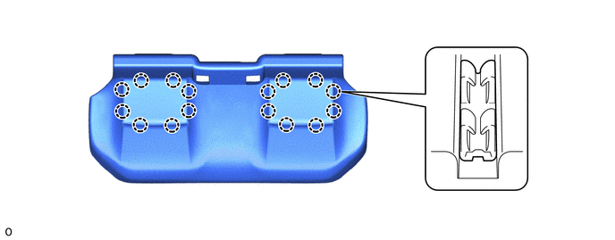
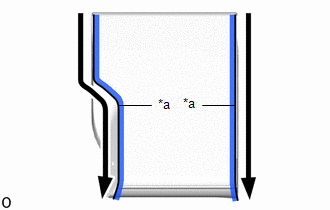
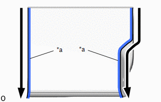
(c) w/o Occupant Classification System:
(1) Engage the hooks and hook and loop fastener to install the bench type rear seat cushion cover.
.png)
|
*a |
Hook and Loop Fastener |
- |
- |
NOTICE:
Be careful not to damage the bench type rear seat cushion cover.
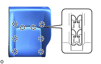
(d) w/ Occupant Classification System:
(1) Engage the hooks and hook and loop fastener to install the bench type rear seat cushion cover.
.png)
|
*a |
Hook and Loop Fastener |
- |
- |
NOTICE:
Be careful not to damage the bench type rear seat cushion cover.
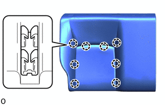
2. INSTALL REAR NO. 2 SEAT COVER BEZEL (w/ Occupant Classification System)
|
(a) Install the rear No. 2 seat cover bezel with the 3 screws. |
|
.png)
3. INSTALL REAR NO. 1 SEAT COVER BEZEL (w/ Occupant Classification System)
HINT:
Use the same procedure for the No. 1 seat cover bezel and No. 2 seat cover bezel.
4. INSTALL REAR DOOR SCUFF PANEL LH (w/ Occupant Classification System)
|
(a) Engage the claws to install the rear door scuff panel LH. |
|
.png)
5. INSTALL REAR DOOR SCUFF PANEL RH (w/ Occupant Classification System)
HINT:
Use the same procedure for the RH side and LH side.
6. INSTALL REAR SEATBACK LOCK ASSEMBLY LH (for LH Side)
|
(a) Engage the guides to install the rear seatback lock assembly LH. |
|
.png)
(b) Install the 2 bolts.
Torque:
30 N·m {306 kgf·cm, 22 ft·lbf}
7. INSTALL SEPARATE TYPE REAR SEATBACK COVER (for LH Side)
NOTICE:
When installing a separate type rear seatback cover, refer to Precaution in order to prevent wrinkles from forming.
Click here
|
(a) Engage the claws to install the separate type rear seatback cover to the separate type rear seatback pad LH. NOTICE: Be careful not to damage the separate type rear seatback cover. |
|
8. INSTALL SEPARATE TYPE REAR SEATBACK COVER WITH PAD (for LH Side)
|
(a) Install the separate type rear seatback cover with pad to the rear seatback frame sub-assembly LH. |
|
.png)
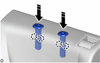
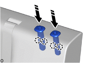
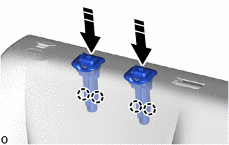
9. INSTALL REAR SEAT HEADREST SUPPORT (for LH Side)
(a) w/o Occupant Classification System:
(1) Engage the claws to install the 2 rear seat headrest supports as shown in the illustration.
.png) |
Install in this Direction |
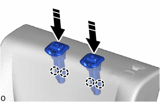
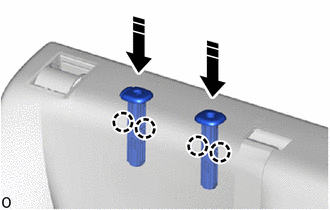
(b) w/ Occupant Classification System:
|
|
Install in this Direction |
(1) Engage the claws to install the 2 rear seat headrest supports as shown in the illustration.
10. INSTALL REAR SEATBACK BOARD SUB-ASSEMBLY LH (for LH Side)
|
(a) Engage the guides and claws to install the rear seatback board sub-assembly LH. |
|
.png)
|
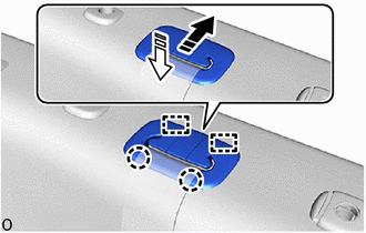
(b) Close the 2 fasteners as shown in the illustration. |
|
|
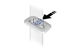
(c) Engage the hook. |
|
.png)
11. INSTALL REAR SEATBACK LOCK CONTROL BEZEL (for LH Side)
|
(a) Engage the hooks to the separate type rear seatback cover. |
|
.png)
|
(b) Engage the claws to install a new rear seatback lock control bezel. |
|
.png)
12. INSTALL REAR SEATBACK LOCK ASSEMBLY RH (for RH Side)
|
(a) Engage the guides to install the rear seatback lock assembly RH. |
|
.png)
(b) Install the 2 bolts.
Torque:
30 N·m {306 kgf·cm, 22 ft·lbf}
13. INSTALL REAR CENTER SEAT OUTER BELT ASSEMBLY (for RH Side)
Click here
14. INSTALL SEPARATE TYPE REAR SEATBACK COVER (for RH Side)
NOTICE:
When installing a separate type rear seatback cover, refer to Precaution in order to prevent wrinkles from forming.
Click here
|
(a) Engage the claws to install the separate type rear seatback cover to the separate type rear seatback pad RH. NOTICE: Be careful not to damage the separate type rear seatback cover. |
|
15. INSTALL SEPARATE TYPE REAR SEATBACK COVER WITH PAD (for RH Side)
|
(a) Pass the rear center seat outer belt assembly through the separate type rear seatback cover with pad and temporarily install the separate type rear seatback cover with pad to the rear seatback frame sub-assembly RH as shown in the illustration. |
|
.png)
16. INSTALL REAR SEAT CENTER HEADREST SUPPORT (for RH Side)
(a) Engage the claws to install the 2 rear seat center headrest supports as shown in the illustration.
|
|
Install in this Direction |
17. INSTALL REAR SEAT HEADREST SUPPORT (for RH Side)
(a) w/o Occupant Classification System:
(1) Engage the claws to install the 2 rear seat headrest supports as shown in the illustration.
|
|
Install in this Direction |
(b) w/ Occupant Classification System:
(1) Engage the claws to install the 2 rear seat headrest supports as shown in the illustration.
|
|
Install in this Direction |
18. INSTALL REAR SEATBACK BOARD SUB-ASSEMBLY RH (for RH Side)
|
(a) Engage the guides and claws to install the rear seatback board sub-assembly RH. |
|
.png)
|
(b) Close the 2 fasteners as shown in the illustration. |
|
|
(c) Engage the hook. |
|
19. INSTALL REAR SEATBACK LOCK CONTROL BEZEL (for RH Side)
|
(a) Engage the hooks to the separate type rear seatback cover. |
|
.png)
|
(b) Engage the claws to install a new rear seatback lock control bezel. |
|
.png)
20. INSTALL REAR SEAT SHOULDER BELT HOLE COVER (for RH Side)
|
(a) Install the rear seat shoulder belt hole cover. |
|
.png)
21. INSTALL SEAT BELT ANCHOR COVER CAP (for RH Side)
(a) Engage the guides to install the seat belt anchor cover cap as shown in the illustration.
|
|
Install in this Direction |
(b) Engage the guides and claws to install the rear seat shoulder belt cover with seat belt anchor cover cap as shown in the illustration.
|
|
Install in this Direction (1) |
.png) |
Install in this Direction (2) |
 Installation
INSTALLATION
CAUTION / NOTICE / HINT
CAUTION:
Wear protective gloves. Sharp areas on the parts may injure your hands.
PROCEDURE
1. INSTALL REAR SEAT CUSHION LOCK HOOK
(a) Engage the claws to ins ...
 Seat Heater Control
Components
COMPONENTS
ILLUSTRATION
*1
SEAT HEATER CONTROL SUB-ASSEMBLY
-
-
Removal
REMOVAL
CAUTION / NOTICE / HINT
The necessary proce ...
Other materials:
Toyota CH-R Service Manual > Charging System: Diagnostic Trouble Code Chart
DIAGNOSTIC TROUBLE CODE CHART
Charging System
DTC No.
Detection Item
Link
P161A
Lost Communication with Alternator
...
Toyota CH-R Service Manual > Power Steering System: How To Proceed With Troubleshooting
CAUTION / NOTICE / HINT
HINT:
Use these procedures to troubleshoot the power steering system.
*: Use the Techstream.
PROCEDURE
1.
VEHICLE BROUGHT TO WORKSHOP
NEXT
2.
...
Toyota C-HR (AX20) 2023-2026 Owner's Manual
Toyota CH-R Owners Manual
- For safety and security
- Instrument cluster
- Operation of each component
- Driving
- Interior features
- Maintenance and care
- When trouble arises
- Vehicle specifications
- For owners
Toyota CH-R Service Manual
- Introduction
- Maintenance
- Audio / Video
- Cellular Communication
- Navigation / Multi Info Display
- Park Assist / Monitoring
- Brake (front)
- Brake (rear)
- Brake Control / Dynamic Control Systems
- Brake System (other)
- Parking Brake
- Axle And Differential
- Drive Shaft / Propeller Shaft
- K114 Cvt
- 3zr-fae Battery / Charging
- Networking
- Power Distribution
- Power Assist Systems
- Steering Column
- Steering Gear / Linkage
- Alignment / Handling Diagnosis
- Front Suspension
- Rear Suspension
- Tire / Wheel
- Tire Pressure Monitoring
- Door / Hatch
- Exterior Panels / Trim
- Horn
- Lighting (ext)
- Mirror (ext)
- Window / Glass
- Wiper / Washer
- Door Lock
- Heating / Air Conditioning
- Interior Panels / Trim
- Lighting (int)
- Meter / Gauge / Display
- Mirror (int)
- Power Outlets (int)
- Pre-collision
- Seat
- Seat Belt
- Supplemental Restraint Systems
- Theft Deterrent / Keyless Entry

0.0074