Toyota CH-R Service Manual: Ambient Temperature Sensor
Components
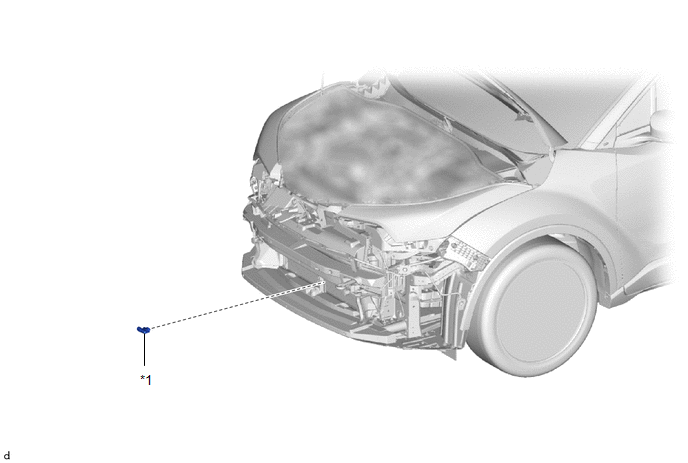
COMPONENTS
ILLUSTRATION
|
*1 |
THERMISTOR ASSEMBLY |
- |
- |
Removal
REMOVAL
PROCEDURE
1. REMOVE FRONT BUMPER ASSEMBLY
Click here
.gif)
2. REMOVE THERMISTOR ASSEMBLY
|
(a) Disconnect the connector. |
|
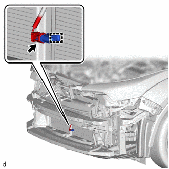
(b) Disengage the clamp to remove the thermistor assembly.
Inspection
INSPECTION
PROCEDURE
1. INSPECT THERMISTOR ASSEMBLY
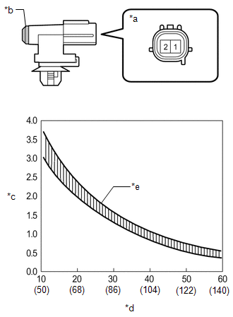
(a) Check the resistance.
|
(1) Measure the resistance according to the value(s) in the table below. Standard resistance:
NOTICE:
HINT: As the temperature increases, the resistance decreases (see the graph). If the specified condition is not met, replace the thermistor assembly. |
|
Installation
INSTALLATION
PROCEDURE
1. INSTALL THERMISTOR ASSEMBLY
|
(a) Engage the clamp to install the thermistor assembly. |
|
.png)
(b) Connect the connector.
2. INSTALL FRONT BUMPER ASSEMBLY
Click here
.gif)
 Installation
INSTALLATION
PROCEDURE
1. INSTALL LOWER DEFROSTER NOZZLE ASSEMBLY
(a) Engage the claws to install the lower defroster nozzle assembly.
2. ...
 Blower Resistor
Components
COMPONENTS
ILLUSTRATION
*A
for Single Type
-
-
*1
BLOWER RESISTOR
*2
NO. 2 INSTRUMENT PA ...
Other materials:
Toyota CH-R Service Manual > Charging System: Freeze Frame Data
FREEZE FRAME DATA
DESCRIPTION
The ECM records vehicle and driving condition information as freeze frame data
the moment a DTC is stored. When troubleshooting, freeze frame data can be helpful
in determining whether the vehicle was moving or stationary, whether the engine
was warmed up or not ...
Toyota CH-R Service Manual > Power Window Control System: Front Passenger Side Power Window Auto Up / Down Function does not Operate with
Front Passenger Side Power Window Switch
DESCRIPTION
If the manual up and down functions operate normally but the auto up and down
functions do not, the power window control system may be in fail-safe mode.
If power window initialization has not been performed, the auto up and down functions
will not operate.
Click here
WIRING ...
Toyota C-HR (AX20) 2023-2026 Owner's Manual
Toyota CH-R Owners Manual
- For safety and security
- Instrument cluster
- Operation of each component
- Driving
- Interior features
- Maintenance and care
- When trouble arises
- Vehicle specifications
- For owners
Toyota CH-R Service Manual
- Introduction
- Maintenance
- Audio / Video
- Cellular Communication
- Navigation / Multi Info Display
- Park Assist / Monitoring
- Brake (front)
- Brake (rear)
- Brake Control / Dynamic Control Systems
- Brake System (other)
- Parking Brake
- Axle And Differential
- Drive Shaft / Propeller Shaft
- K114 Cvt
- 3zr-fae Battery / Charging
- Networking
- Power Distribution
- Power Assist Systems
- Steering Column
- Steering Gear / Linkage
- Alignment / Handling Diagnosis
- Front Suspension
- Rear Suspension
- Tire / Wheel
- Tire Pressure Monitoring
- Door / Hatch
- Exterior Panels / Trim
- Horn
- Lighting (ext)
- Mirror (ext)
- Window / Glass
- Wiper / Washer
- Door Lock
- Heating / Air Conditioning
- Interior Panels / Trim
- Lighting (int)
- Meter / Gauge / Display
- Mirror (int)
- Power Outlets (int)
- Pre-collision
- Seat
- Seat Belt
- Supplemental Restraint Systems
- Theft Deterrent / Keyless Entry

0.0081