Toyota CH-R Service Manual: Blower Resistor
Components
COMPONENTS
ILLUSTRATION
|
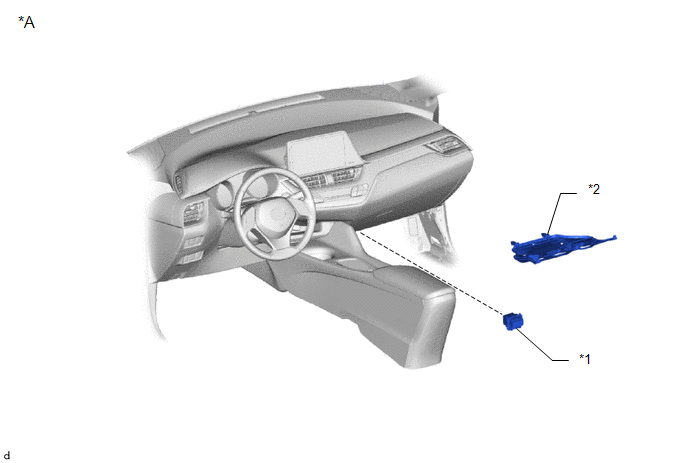
*A |
for Single Type |
- |
- |
|
*1 |
BLOWER RESISTOR |
*2 |
NO. 2 INSTRUMENT PANEL UNDER COVER SUB-ASSEMBLY |
ILLUSTRATION
|
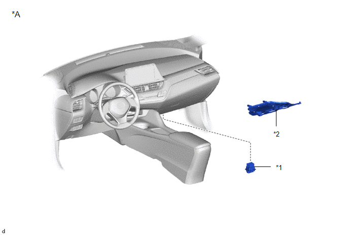
*A |
for Dual Type |
- |
- |
|
*1 |
BLOWER RESISTOR |
*2 |
NO. 2 INSTRUMENT PANEL UNDER COVER SUB-ASSEMBLY |
Installation
INSTALLATION
PROCEDURE
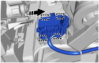
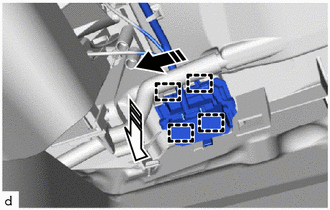
1. INSTALL BLOWER RESISTOR (for Single Type)
(a) Connect the connector.
(b) Engage the guides and install the blower resistor as shown in the illustration.
.png) |
Remove in this Direction |
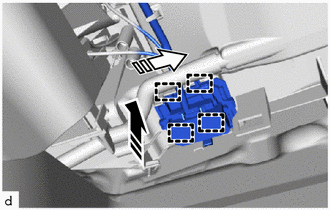
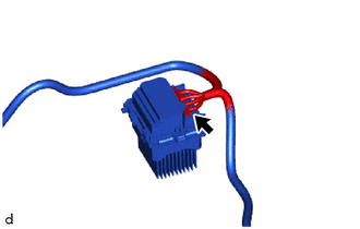
2. INSTALL BLOWER RESISTOR (for Dual Type)
(a) Connect the connector.
(b) Engage the guides and install the blower resistor as shown in the illustration.
|
|
Remove in this Direction (1) |
.png) |
Remove in this Direction (2) |
3. INSTALL NO. 2 INSTRUMENT PANEL UNDER COVER SUB-ASSEMBLY
Click here
.gif)
Removal
REMOVAL
PROCEDURE
1. REMOVE NO. 2 INSTRUMENT PANEL UNDER COVER SUB-ASSEMBLY
Click here
.gif)
2. REMOVE BLOWER RESISTOR (for Single Type)
(a) Disengage the guides and separate the blower resistor as shown in the illustration.

.png) |
Remove in this Direction |
|
(b) Disconnect the connector to remove the blower resistor. |
|
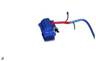
3. REMOVE BLOWER RESISTOR (for Dual Type)
(a) Disengage the guides and separate the blower resistor as shown in the illustration.
|
|
Remove in this Direction (1) |
.png) |
Remove in this Direction (2) |
|
(b) Disconnect the connector to remove the blower resistor. |
|
 Ambient Temperature Sensor
Components
COMPONENTS
ILLUSTRATION
*1
THERMISTOR ASSEMBLY
-
-
Removal
REMOVAL
PROCEDURE
1. REMOVE FRONT BUMPER ASSEMBLY
Click here
...

Other materials:
Toyota CH-R Owners Manual > Child restraint systems: Using an anchor bracket (for top tether strap)
■ Anchor brackets (for top tether strap) Anchor brackets are
provided for each rear seat.
Use anchor brackets when fixing the top tether strap.
■ Fixing the top tether strap to the anchor bracket Install
the child restraint system in accordance to the operation manual enclosed with the ...
Toyota CH-R Service Manual > Vehicle Stability Control System: ABS does not Operate
DESCRIPTION
When the vehicle stability control system is operating, as the input piston and
output piston are not directly connected, the kickback of the brake pedal is minimal
during ABS operation and the driver may not notice that ABS operated.
CAUTION / NOTICE / HINT
NOTICE:
When replacin ...
Toyota C-HR (AX20) 2023-2026 Owner's Manual
Toyota CH-R Owners Manual
- For safety and security
- Instrument cluster
- Operation of each component
- Driving
- Interior features
- Maintenance and care
- When trouble arises
- Vehicle specifications
- For owners
Toyota CH-R Service Manual
- Introduction
- Maintenance
- Audio / Video
- Cellular Communication
- Navigation / Multi Info Display
- Park Assist / Monitoring
- Brake (front)
- Brake (rear)
- Brake Control / Dynamic Control Systems
- Brake System (other)
- Parking Brake
- Axle And Differential
- Drive Shaft / Propeller Shaft
- K114 Cvt
- 3zr-fae Battery / Charging
- Networking
- Power Distribution
- Power Assist Systems
- Steering Column
- Steering Gear / Linkage
- Alignment / Handling Diagnosis
- Front Suspension
- Rear Suspension
- Tire / Wheel
- Tire Pressure Monitoring
- Door / Hatch
- Exterior Panels / Trim
- Horn
- Lighting (ext)
- Mirror (ext)
- Window / Glass
- Wiper / Washer
- Door Lock
- Heating / Air Conditioning
- Interior Panels / Trim
- Lighting (int)
- Meter / Gauge / Display
- Mirror (int)
- Power Outlets (int)
- Pre-collision
- Seat
- Seat Belt
- Supplemental Restraint Systems
- Theft Deterrent / Keyless Entry

0.0125