Toyota CH-R Service Manual: Speaker Output Short (B15C3)
DESCRIPTION
This DTC is stored when a malfunction occurs in the speakers.
|
DTC No. |
Detection Item |
DTC Detection Condition |
Trouble Area |
|---|---|---|---|
|
B15C3 |
Speaker Output Short |
A short is detected in the speaker output circuit |
|
- *1: w/ Manual (SOS) Switch
WIRING DIAGRAM
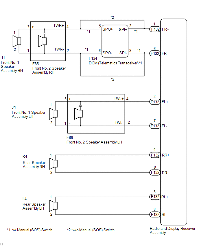
PROCEDURE
|
1. |
CONFIRM MODEL |
(a) Choose the model to be inspected.
|
Result |
Proceed to |
|---|---|
|
w/ Manual (SOS) Switch |
A |
|
w/o Manual (SOS) Switch |
B |
| B | .gif) |
GO TO STEP 5 |
|
.gif)
|
2. |
CHECK HARNESS AND CONNECTOR (RADIO AND DISPLAY RECEIVER ASSEMBLY, DCM(TELEMATICS TRANSCEIVER) OR SPEAKERS - BODY GROUND) |
(a) Disconnect the F132 radio and display receiver assembly connectors.
(b) Disconnect the F134 DCM (telematics transceiver) connector.
(c) Disconnect the F86 front No. 2 speaker assembly LH connector.
(d) Disconnect the K4 and L4 rear speaker assembly connectors.
(e) Measure the resistance according to the value(s) in the table below.
Standard Resistance:
|
Tester Connection |
Condition |
Specified Condition |
|---|---|---|
|
F132-1 (FR+) or F134-2 (SPI+) - Body ground |
Always |
10 kΩ or higher |
|
F132-6 (FR-) or F134-3 (SPI-) - Body ground |
Always |
10 kΩ or higher |
|
F132-2 (FL+) or F86-4 (TWL+) - Body ground |
Always |
10 kΩ or higher |
|
F132-7 (FL-) or F86-2 (TWL-) - Body ground |
Always |
10 kΩ or higher |
|
F132-4 (RR+) or K4-1 - Body ground |
Always |
10 kΩ or higher |
|
F132-9 (RR-) or K4-2 - Body ground |
Always |
10 kΩ or higher |
|
F132-3 (RL+) or L4-1 - Body ground |
Always |
10 kΩ or higher |
|
F132-8 (RL-) or L4-2 - Body ground |
Always |
10 kΩ or higher |
| NG | |
REPAIR OR REPLACE HARNESS OR CONNECTOR |
|
|
3. |
CHECK HARNESS AND CONNECTOR (FRONT NO. 2 SPEAKER ASSEMBLY RH OR DCM (TELEMATICS TRANSCEIVER) - BODY GROUND) |
(a) Disconnect the F85 front No. 2 speaker assembly RH connector.
(b) Disconnect the F134 DCM (telematics transceiver) connector.
(c) Measure the resistance according to the value(s) in the table below.
Standard Resistance:
|
Tester Connection |
Condition |
Specified Condition |
|---|---|---|
|
F85-4 (TWR+) or F134-5 (SPO+) - Body ground |
Always |
10 kΩ or higher |
|
F85-2 (TWR-) or F134-6 (SPO-) - Body ground |
Always |
10 kΩ or higher |
| NG | |
REPAIR OR REPLACE HARNESS OR CONNECTOR |
|
|
4. |
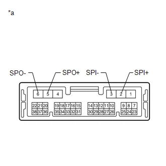
INSPECT DCM (TELEMATICS TRANSCEIVER) |
(a) Remove the DCM (telematics transceiver).
Click here
.gif)
|
(b) Measure the resistance according to the value(s) in the table below. Standard Resistance:
|
|
| OK | |
GO TO STEP 6 |
| NG | |
REPLACE DCM (TELEMATICS TRANSCEIVER) |
|
5. |
CHECK HARNESS AND CONNECTOR (RADIO AND DISPLAY RECEIVER ASSEMBLY OR SPEAKERS - BODY GROUND) |
(a) Disconnect the F132 radio and display receiver assembly connectors.
(b) Disconnect the F85 and F86 front No. 2 speaker assembly connectors.
(c) Disconnect the K4 and L4 rear speaker assembly connectors.
(d) Measure the resistance according to the value(s) in the table below.
Standard Resistance:
|
Tester Connection |
Condition |
Specified Condition |
|---|---|---|
|
F132-1 (FR+) or F85-4 (TWR+) - Body ground |
Always |
10 kΩ or higher |
|
F132-6 (FR-) or F85-2 (TWR-) - Body ground |
Always |
10 kΩ or higher |
|
F132-2 (FL+) or F86-4 (TWL+) - Body ground |
Always |
10 kΩ or higher |
|
F132-7 (FL-) or F86-2 (TWL-) - Body ground |
Always |
10 kΩ or higher |
|
F132-4 (RR+) or K4-1 - Body ground |
Always |
10 kΩ or higher |
|
F132-9 (RR-) or K4-2 - Body ground |
Always |
10 kΩ or higher |
|
F132-3 (RL+) or L4-1 - Body ground |
Always |
10 kΩ or higher |
|
F132-8 (RL-) or L4-2 - Body ground |
Always |
10 kΩ or higher |
| NG | |
REPAIR OR REPLACE HARNESS OR CONNECTOR |
|
|
6. |
CHECK HARNESS AND CONNECTOR (FRONT NO. 1 SPEAKER ASSEMBLY OR FRONT NO. 2 SPEAKER ASSEMBLY - BODY GROUND) |
(a) Disconnect the I1 and J1 front No. 1 speaker assembly connectors.
(b) Disconnect the F85 and F86 front No. 2 speaker assembly connectors.
(c) Measure the resistance according to the value(s) in the table below.
Standard Resistance:
|
Tester Connection |
Condition |
Specified Condition |
|---|---|---|
|
F85-3 (+) or I1-1 - Body ground |
Always |
10 kΩ or higher |
|
F85-1 (-) or I1-2 - Body ground |
Always |
10 kΩ or higher |
|
F86-3 (+) or J1-1 - Body ground |
Always |
10 kΩ or higher |
|
F86-1 (-) or J1-2 - Body ground |
Always |
10 kΩ or higher |
| NG | |
REPAIR OR REPLACE HARNESS OR CONNECTOR |
|
|
7. |
INSPECT FRONT NO. 1 SPEAKER ASSEMBLY |
(a) Remove the front No. 1 speaker assembly.
Click here
(b) Inspect the front No. 1 speaker assembly.
Click here
| NG | |
REPLACE FRONT NO. 1 SPEAKER ASSEMBLY |
|
|
8. |
INSPECT FRONT NO. 2 SPEAKER ASSEMBLY |
(a) Remove the front No. 2 speaker assembly.
Click here
(b) Inspect the front No. 2 speaker assembly.
Click here
(c) Clear the DTCs.
Click here
(d) Recheck for DTCs and check that no DTCs are output.
Body Electrical > Navigation System > Trouble CodesOK:
No DTCs are output.
| OK | |
END |
|
|
9. |
INSPECT REAR SPEAKER ASSEMBLY |
(a) Remove the rear speaker assembly.
Click here
(b) Inspect the rear speaker assembly.
Click here
| OK | |
REPLACE RADIO AND DISPLAY RECEIVER ASSEMBLY |
| NG | |
REPLACE REAR SPEAKER ASSEMBLY |
 Telematics Transceiver Disconnected (B15DB)
DESCRIPTION
If the radio and display receiver assembly cannot detect the DCM (telematics
transceiver) for a certain period of time (90 seconds) after the ignition switch
is turned on (ACC) and th ...
 GPS Antenna Connection Malfunction(short) (B15C0,B15C1)
DESCRIPTION
These DTCs are stored when a malfunction occurs in the navigation antenna assembly.
DTC No.
Detection Item
DTC Detection Condition
Trouble Are ...
Other materials:
Toyota CH-R Owners Manual > Steps to take in an emergency: If your vehicle overheats
The following may indicate that your vehicle is overheating.
The needle of the engine coolant temperature gauge enters the red zone or
a loss of engine power is experienced (for example, the vehicle speed does not
increase).
Steam comes out from under the hood.
Correction procedures
...
Toyota CH-R Service Manual > Pre-collision System: Front Radar Sensor (C1A10)
DESCRIPTION
C1A10 is output when there is an internal malfunction in the millimeter wave
radar sensor assembly.
DTC No.
Detection Item
DTC Detection Condition
Trouble Area
C1A10
Front Radar Sensor
After the igniti ...
Toyota C-HR (AX20) 2023-2026 Owner's Manual
Toyota CH-R Owners Manual
- For safety and security
- Instrument cluster
- Operation of each component
- Driving
- Interior features
- Maintenance and care
- When trouble arises
- Vehicle specifications
- For owners
Toyota CH-R Service Manual
- Introduction
- Maintenance
- Audio / Video
- Cellular Communication
- Navigation / Multi Info Display
- Park Assist / Monitoring
- Brake (front)
- Brake (rear)
- Brake Control / Dynamic Control Systems
- Brake System (other)
- Parking Brake
- Axle And Differential
- Drive Shaft / Propeller Shaft
- K114 Cvt
- 3zr-fae Battery / Charging
- Networking
- Power Distribution
- Power Assist Systems
- Steering Column
- Steering Gear / Linkage
- Alignment / Handling Diagnosis
- Front Suspension
- Rear Suspension
- Tire / Wheel
- Tire Pressure Monitoring
- Door / Hatch
- Exterior Panels / Trim
- Horn
- Lighting (ext)
- Mirror (ext)
- Window / Glass
- Wiper / Washer
- Door Lock
- Heating / Air Conditioning
- Interior Panels / Trim
- Lighting (int)
- Meter / Gauge / Display
- Mirror (int)
- Power Outlets (int)
- Pre-collision
- Seat
- Seat Belt
- Supplemental Restraint Systems
- Theft Deterrent / Keyless Entry

0.0095