Toyota CH-R Service Manual: GPS Antenna Connection Malfunction(short) (B15C0,B15C1)
DESCRIPTION
These DTCs are stored when a malfunction occurs in the navigation antenna assembly.
|
DTC No. |
Detection Item |
DTC Detection Condition |
Trouble Area |
|---|---|---|---|
|
B15C0 |
GPS Antenna Connection Malfunction(short) |
Navigation antenna malfunction |
|
|
B15C1 |
GPS Antenna Connection Malfunction(break) |
Navigation antenna power source malfunction |
|
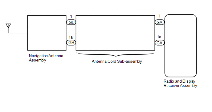
WIRING DIAGRAM
CAUTION / NOTICE / HINT
NOTICE:
- Depending on the parts that are replaced during vehicle inspection or
maintenance, performing initialization, registration or calibration may
be needed. Refer to Precaution for Audio and Visual System.
Click here
.gif)
- When replacing the navigation ECU, always replace it with a new one.
If a navigation ECU which was installed to another vehicle is used, the
following may occur:
- A communication malfunction DTC is stored.
- The radio and display receiver assembly may not operate normally.
- Check that the antenna cord sub-assembly (for navigation antenna) is
properly installed and does not have any sharp bends, pinching or loose
connections before performing following procedure.
Click here
PROCEDURE
|
1. |
CHECK DTC |
(a) Clear the DTCs.
Body Electrical > Navigation System > Clear DTCs(b) Recheck for DTCs and check that no DTCs are output.
Body Electrical > Navigation System > Trouble CodesOK:
No DTCs are output.
| OK | .gif) |
USE SIMULATION METHOD TO CHECK |
|
.gif)
|
2. |
REPLACE ANTENNA CORD SUB-ASSEMBLY |
(a) Replace the antenna cord sub-assembly with a new or known good one.
Click here
| NG | |
REPLACE ANTENNA CORD SUB-ASSEMBLY |
|
|
3. |
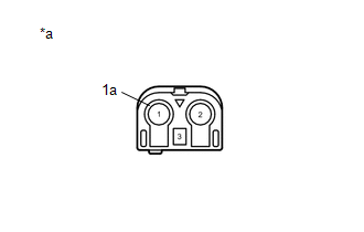
INSPECT NAVIGATION ANTENNA ASSEMBLY |
(a) Remove the navigation antenna assembly.
Click here
|
(b) Measure the resistance according to the value(s) in the table below. Standard Resistance:
|
|
| OK | |
REPLACE RADIO AND DISPLAY RECEIVER ASSEMBLY |
| NG | |
REPLACE NAVIGATION ANTENNA ASSEMBLY |
 Speaker Output Short (B15C3)
DESCRIPTION
This DTC is stored when a malfunction occurs in the speakers.
DTC No.
Detection Item
DTC Detection Condition
Trouble Area
B15 ...
 AV Signal Stoppage (Low Battery Voltage) (B158F)
DESCRIPTION
This DTC is stored when a video or audio signal is interrupted due to battery
voltage input to the radio and display receiver assembly dropping temporarily.
DTC No.
...
Other materials:
Toyota CH-R Owners Manual > Air conditioning system: Other functions
■ Switching between outside air and recirculated air modes
Press
.
The mode switches between outside air mode (indicator off) and recirculated air
mode (indicator on) each time
is pressed.
■ Defogging the windshield Defoggers are used to defog the windshield
and front side windows.
Pr ...
Toyota CH-R Service Manual > Manual Headlight Beam Level Control System: Precaution
PRECAUTION
EXPRESSIONS OF IGNITION SWITCH
The type of ignition switch used on this model differs depending on the specifications
of the vehicle. The expressions listed in the table below are used in this section.
Expression
Ignition Switch (Position)
Engine Swit ...
Toyota C-HR (AX20) 2023-2026 Owner's Manual
Toyota CH-R Owners Manual
- For safety and security
- Instrument cluster
- Operation of each component
- Driving
- Interior features
- Maintenance and care
- When trouble arises
- Vehicle specifications
- For owners
Toyota CH-R Service Manual
- Introduction
- Maintenance
- Audio / Video
- Cellular Communication
- Navigation / Multi Info Display
- Park Assist / Monitoring
- Brake (front)
- Brake (rear)
- Brake Control / Dynamic Control Systems
- Brake System (other)
- Parking Brake
- Axle And Differential
- Drive Shaft / Propeller Shaft
- K114 Cvt
- 3zr-fae Battery / Charging
- Networking
- Power Distribution
- Power Assist Systems
- Steering Column
- Steering Gear / Linkage
- Alignment / Handling Diagnosis
- Front Suspension
- Rear Suspension
- Tire / Wheel
- Tire Pressure Monitoring
- Door / Hatch
- Exterior Panels / Trim
- Horn
- Lighting (ext)
- Mirror (ext)
- Window / Glass
- Wiper / Washer
- Door Lock
- Heating / Air Conditioning
- Interior Panels / Trim
- Lighting (int)
- Meter / Gauge / Display
- Mirror (int)
- Power Outlets (int)
- Pre-collision
- Seat
- Seat Belt
- Supplemental Restraint Systems
- Theft Deterrent / Keyless Entry

0.0075