Toyota CH-R Service Manual: Components
COMPONENTS
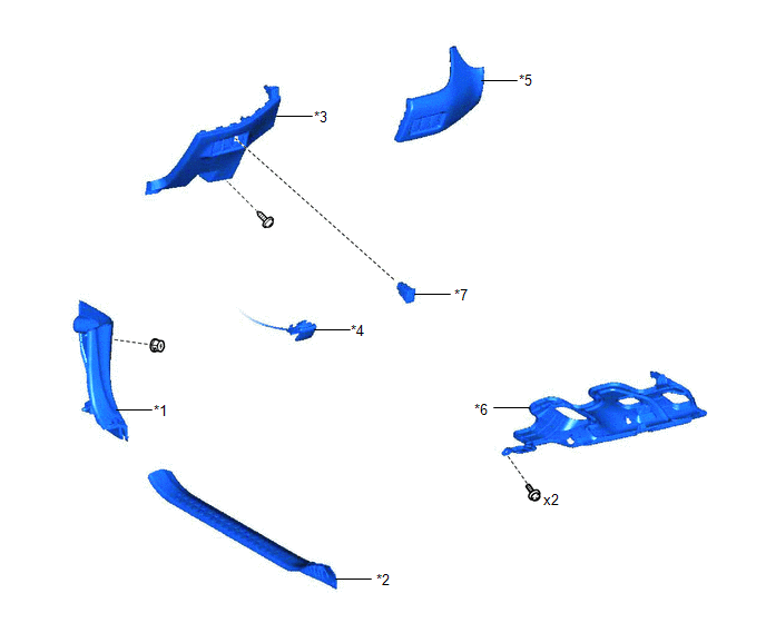
ILLUSTRATION
|
*1 |
COWL SIDE TRIM BOARD LH |
*2 |
FRONT DOOR SCUFF PLATE LH |
|
*3 |
FUSE BOX OPENING COVER |
*4 |
HOOD LOCK CONTROL LEVER SUB-ASSEMBLY |
|
*5 |
INSTRUMENT CLUSTER FINISH PANEL SUB-ASSEMBLY |
*6 |
NO. 1 INSTRUMENT PANEL UNDER COVER SUB-ASSEMBLY |
|
*7 |
STEERING HEATER SWITCH |
- |
- |

 Removal
REMOVAL
PROCEDURE
1. REMOVE FRONT DOOR SCUFF PLATE LH
Click here
2. REMOVE COWL SIDE TRIM BOARD LH
Click here
3. REMOVE NO. 1 INSTRUMENT PANEL UNDER COVER SUB-ASSEMBLY
Click here
4 ...
Other materials:
Toyota CH-R Service Manual > Can Communication System: Check Bus 2 Line for Short to +B
DESCRIPTION
There may be a short circuit between one of the CAN bus lines and +B when no
resistance exists between terminal 18 (CA4H) of the central gateway ECU (network
gateway ECU) and terminal 16 (BAT) of the DLC3, or terminal 17 (CA4L) of the central
gateway ECU (network gateway ECU) and ...
Toyota CH-R Service Manual > Smart Key System(for Start Function): Engine does not Start
DESCRIPTION
When the electrical key transmitter sub-assembly is in the cabin and the engine
switch is pressed, the certification ECU (smart key ECU assembly) receives a signal
and changes the power source mode. Additionally, when the shift lever is in P and
the brake pedal is depressed, the e ...
Toyota C-HR (AX20) 2023-2026 Owner's Manual
Toyota CH-R Owners Manual
- For safety and security
- Instrument cluster
- Operation of each component
- Driving
- Interior features
- Maintenance and care
- When trouble arises
- Vehicle specifications
- For owners
Toyota CH-R Service Manual
- Introduction
- Maintenance
- Audio / Video
- Cellular Communication
- Navigation / Multi Info Display
- Park Assist / Monitoring
- Brake (front)
- Brake (rear)
- Brake Control / Dynamic Control Systems
- Brake System (other)
- Parking Brake
- Axle And Differential
- Drive Shaft / Propeller Shaft
- K114 Cvt
- 3zr-fae Battery / Charging
- Networking
- Power Distribution
- Power Assist Systems
- Steering Column
- Steering Gear / Linkage
- Alignment / Handling Diagnosis
- Front Suspension
- Rear Suspension
- Tire / Wheel
- Tire Pressure Monitoring
- Door / Hatch
- Exterior Panels / Trim
- Horn
- Lighting (ext)
- Mirror (ext)
- Window / Glass
- Wiper / Washer
- Door Lock
- Heating / Air Conditioning
- Interior Panels / Trim
- Lighting (int)
- Meter / Gauge / Display
- Mirror (int)
- Power Outlets (int)
- Pre-collision
- Seat
- Seat Belt
- Supplemental Restraint Systems
- Theft Deterrent / Keyless Entry

0.0073