Toyota CH-R Service Manual: Telematics Transceiver Disconnected (B15DB)
DESCRIPTION
If the radio and display receiver assembly cannot detect the DCM (telematics transceiver) for a certain period of time (90 seconds) after the ignition switch is turned on (ACC) and the radio and display receiver assembly confirms that the information is missing by checking past DCM (telematics transceiver) recognition information (registered information), this DTC will be stored.
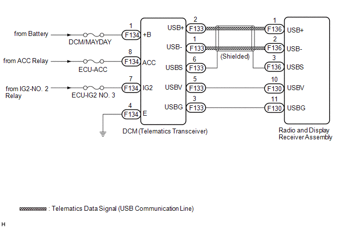
The telematics system uses USB communication between devices. If an open, short, short to +B or short to ground occurs in the USB circuit, communication is interrupted and the telematics system will not operate normally.
|
DTC No. |
Detection Item |
DTC Detection Condition |
Trouble Area |
|---|---|---|---|
|
B15DB |
Telematics Transceiver Disconnected |
DCM (telematics transceiver) disconnected |
|
HINT:
This DTC may be stored due to environmental reasons such as electrical noise or interference.
WIRING DIAGRAM
CAUTION / NOTICE / HINT
NOTICE:
- Depending on the parts that are replaced during vehicle inspection or
maintenance, performing initialization, registration or calibration may
be needed. Refer to Precaution for Audio and Visual System.
Click here
.gif)
- When replacing the radio and display receiver assembly, always replace
it with a new one. If a radio and display receiver assembly which was installed
to another vehicle is used, the following may occur:
- A communication malfunction DTC is stored.
- The radio and display receiver assembly may not operate normally.
- Inspect the fuses for circuits related to this system before performing the following procedure.
- Before replacing the DCM (telematics transceiver), refer to Registration.
Click here
PROCEDURE
|
1. |
CHECK DTC |
(a) Clear the DTCs.
Body Electrical > Navigation System > Clear DTCs(b) Turn the ignition switch off.
(c) Turn the ignition switch to ON and wait for 90 seconds.
(d) Recheck for DTCs and check that no DTCs are output.
Body Electrical > Navigation System > Trouble CodesOK:
No DTCs are output.
| OK | .gif) |
USE SIMULATION METHOD TO CHECK |
|
.gif)
|
2. |
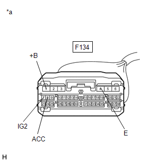
CHECK HARNESS AND CONNECTOR (DCM (TELEMATICS TRANSCEIVER) POWER SOURCE) |
(a) Disconnect the DCM (telematics transceiver) connector.
(b) Measure the resistance according to the value(s) in the table below.
Standard Resistance:
|
Tester Connection |
Condition |
Specified Condition |
|---|---|---|
|
F134-4 (E) - Body ground |
Always |
Below 1 Ω |
|
(c) Measure the voltage according to the value(s) in the table below. Standard Voltage:
|
|
| NG | |
REPAIR OR REPLACE HARNESS OR CONNECTOR |
|
|
3. |
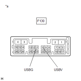
CHECK HARNESS AND CONNECTOR (RADIO AND DISPLAY RECEIVER ASSEMBLY - DCM (TELEMATICS TRANSCEIVER)) |
(a) Disconnect the F130 radio and display receiver assembly connector.
(b) Disconnect the F133 DCM (telematics transceiver) connector.
(c) Measure the resistance according to the value(s) in the table below.
Standard Resistance:
|
Tester Connection |
Condition |
Specified Condition |
|---|---|---|
|
F130-10 (USBV) - F133-5 (USBV) |
Always |
Below 1 Ω |
|
F130-11 (USBG) - F133-3 (USBG) |
Always |
Below 1 Ω |
|
F130-10 (USBV) or F133-5 (USBV) - Body ground |
Always |
10 kΩ or higher |
|
F130-11 (USBG) or F133-3 (USBG) - Body ground |
Always |
10 kΩ or higher |
| NG | |
REPAIR OR REPLACE HARNESS OR CONNECTOR |
|
|
4. |
INSPECT RADIO AND DISPLAY RECEIVER ASSEMBLY |
(a) Disconnect the radio and display receiver assembly connector.
|
(b) Measure the resistance according to the value(s) in the table below. Standard Resistance:
|
|
(c) Measure the voltage according to the value(s) in the table below.
Standard Voltage:
|
Tester Connection |
Switch Condition |
Specified Condition |
|---|---|---|
|
F130-10 (USBV) - F130-11 (USBG) |
ignition switch ACC |
4.75 to 5.25 V |
| NG | |
REPLACE RADIO AND DISPLAY RECEIVER ASSEMBLY |
|
|
5. |
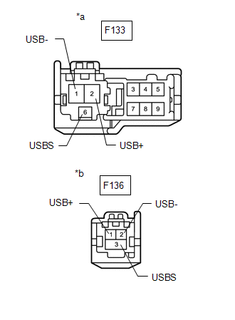
CHECK HARNESS AND CONNECTOR (DCM (TELEMATICS TRANSCEIVER) - RADIO AND DISPLAY RECEIVER ASSEMBLY) |
(a) Disconnect the F133 DCM (telematics transceiver) connector.
(b) Disconnect the F136 radio and display receiver assembly connector.
|
(c) Measure the resistance according to the value(s) in the table below. Standard Resistance:
|
|
| NG | |
REPAIR OR REPLACE HARNESS OR CONNECTOR |
|
|
6. |
CHECK DCM (TELEMATICS TRANSCEIVER) |
(a) Replace the DCM (telematics transceiver) with a new one.
Click here
(b) Clear the DTCs.
Body Electrical > Navigation System > Clear DTCs(c) Turn the ignition switch off.
(d) Turn the ignition switch to ON and wait for 90 seconds.
(e) Recheck for DTCs and check that no DTCs are output.
Body Electrical > Navigation System > Trouble CodesOK:
No DTCs are output.
| OK | |
END (DCM [TELEMATICS TRANSCEIVER] IS DEFECTIVE) |
| NG | |
REPLACE RADIO AND DISPLAY RECEIVER ASSEMBLY |
 Air Conditioner ECU Vehicle Information Reading/Writing Processor Malfunction
(B15F5)
Air Conditioner ECU Vehicle Information Reading/Writing Processor Malfunction
(B15F5)
DESCRIPTION
This DTC is stored when items controlled by the air conditioning amplifier assembly
cannot be customized via the audio and visual system vehicle customization screen.
HINT:
The air co ...
 Speaker Output Short (B15C3)
DESCRIPTION
This DTC is stored when a malfunction occurs in the speakers.
DTC No.
Detection Item
DTC Detection Condition
Trouble Area
B15 ...
Other materials:
Toyota CH-R Service Manual > Air Conditioning System(for Automatic Air Conditioning System With Top-mounted
Air Conditioner Pressure Sensor): Pressure Sensor Circuit (B1423)
DESCRIPTION
This DTC is stored if refrigerant pressure on the high pressure side is extremely
low (176 kPa (1.8 kgf/cm2, 26 psi) or less)*1, (195 kPa (2.0 kgf/cm2, 28 psi) or
less)*2 or extremely high (3025 kPa (30.8 kgf/cm2, 439 psi) or more)*1, (2812 kPa
(28.7 kgf/cm2, 408 psi) or more)*2. ...
Toyota CH-R Service Manual > Airbag System: Lost communication with Side Airbag Sensor RH (B1622/81,B1623/81,B1632/81,B1633/81,B1642/81,B1643/81,B166D/81,B166E/81)
DESCRIPTION
The side collision sensor RH circuit (bus 1) consists of the airbag sensor assembly,
door side airbag sensor RH, No. 1 side airbag sensor RH and No. 2 side airbag sensor
RH.
The door side airbag sensor RH, No. 1 side airbag sensor RH and No. 2 side airbag
sensor RH detect impacts ...
Toyota C-HR (AX20) 2023-2026 Owner's Manual
Toyota CH-R Owners Manual
- For safety and security
- Instrument cluster
- Operation of each component
- Driving
- Interior features
- Maintenance and care
- When trouble arises
- Vehicle specifications
- For owners
Toyota CH-R Service Manual
- Introduction
- Maintenance
- Audio / Video
- Cellular Communication
- Navigation / Multi Info Display
- Park Assist / Monitoring
- Brake (front)
- Brake (rear)
- Brake Control / Dynamic Control Systems
- Brake System (other)
- Parking Brake
- Axle And Differential
- Drive Shaft / Propeller Shaft
- K114 Cvt
- 3zr-fae Battery / Charging
- Networking
- Power Distribution
- Power Assist Systems
- Steering Column
- Steering Gear / Linkage
- Alignment / Handling Diagnosis
- Front Suspension
- Rear Suspension
- Tire / Wheel
- Tire Pressure Monitoring
- Door / Hatch
- Exterior Panels / Trim
- Horn
- Lighting (ext)
- Mirror (ext)
- Window / Glass
- Wiper / Washer
- Door Lock
- Heating / Air Conditioning
- Interior Panels / Trim
- Lighting (int)
- Meter / Gauge / Display
- Mirror (int)
- Power Outlets (int)
- Pre-collision
- Seat
- Seat Belt
- Supplemental Restraint Systems
- Theft Deterrent / Keyless Entry

0.007