Toyota CH-R Service Manual: Windshield Deicer does not Operate
DESCRIPTION
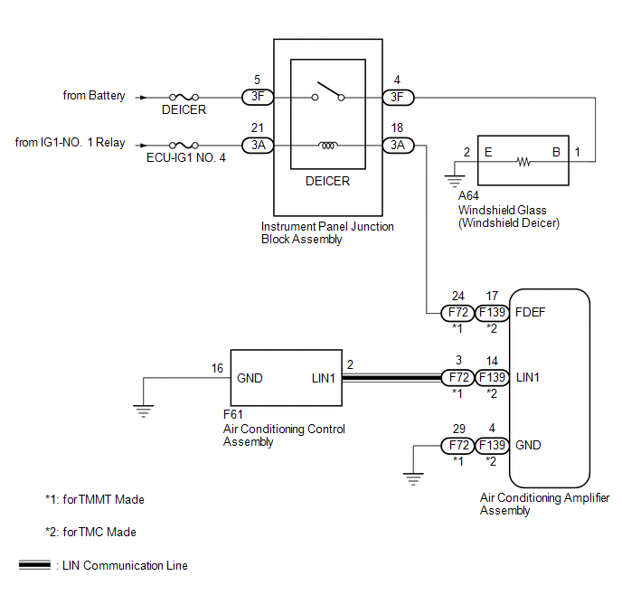
When the windshield deicer switch on the air conditioning control assembly is pressed, the operation signal is transmitted to the air conditioning amplifier assembly. via LIN communication. When the air conditioning amplifier assembly receives the signal, it turns on the DEICER relay to operate the windshield deicer system.
WIRING DIAGRAM
CAUTION / NOTICE / HINT
NOTICE:
- Inspect the fuses and relay for circuits related to this system before performing the following procedure.
- If the battery voltage becomes low, windshield deicer operation is canceled to prioritize supplying power to the power steering system.
PROCEDURE
|
1. |
CHECK AIR CONDITIONING SYSTEM |
(a) Check air conditioning system.
HINT:
Both the windshield deicer system operation signal and air conditioning system operation signal are transmitted to the air conditioning amplifier assembly via the same communication line.
OK:
The air conditioning system operates normally.
| Result |
Proceed to |
|---|---|
| OK |
A |
| NG (for TMMT Made) |
B |
| NG (for TMC Made) |
C |
| B | .gif) |
GO TO AIR CONDITIONING SYSTEM |
| C | |
GO TO AIR CONDITIONING SYSTEM |
|
.gif)
|
2. |
PERFORM ACTIVE TEST USING TECHSTREAM |
(a) Using the Techstream, perform the Active Test.
Click here
.gif)
|
Tester Display |
Measurement Item |
Control Range |
Diagnostic Note |
|---|---|---|---|
|
Deicer Relay (Front) |
Windshield glass (windshield deicer) |
OFF or ON |
- |
|
Tester Display |
|---|
|
Deicer Relay (Front) |
OK:
The windshield deicer system operates normally.
| NG | |
GO TO STEP 4 |
|
|
3. |
REPLACE AIR CONDITIONING CONTROL ASSEMBLY |
(a) Replace air conditioning control assembly with a new or known good one.
Click here
(b) Check that the window defogger system operates normally.
Click here
| OK | |
END (AIR CONDITIONING CONTROL ASSEMBLY WAS DEFECTIVE) |
| NG | |
REPLACE AIR CONDITIONING AMPLIFIER ASSEMBLY |
|
4. |
CHECK HARNESS AND CONNECTOR (INSTRUMENT PANEL JUNCTION BLOCK ASSEMBLY - BATTERY) |
|
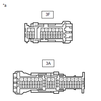
(a) Disconnect the 3F and 3A instrument panel junction block assembly connectors. |
|
(b) Measure the voltage according to the value(s) in the table below.
Standard Voltage:
|
Tester Connection |
Switch Condition |
Specified Condition |
|---|---|---|
|
3F-5 - Body ground |
Always |
11 to 14 V |
|
3A-21 - Body ground |
Ignition switch ON |
11 to 14 V |
| NG | |
REPAIR OR REPLACE HARNESS OR CONNECTOR |
|
|
5. |
CHECK HARNESS AND CONNECTOR (INSTRUMENT PANEL JUNCTION BLOCK ASSEMBLY - AIR CONDITIONING AMPLIFIER ASSEMBLY) |
(a) Disconnect the 3A instrument panel junction block assembly connector.
(b) Disconnect the F72*1 or F139*2 air conditioning amplifier assembly connector.
- *1: for TMMT Made
- *2: for TMC Made
(c) Measure the resistance according to the value(s) in the table below.
Standard Resistance:
for TMMT Made|
Tester Connection |
Condition |
Specified Condition |
|---|---|---|
|
3A-18 - F72-24 (FDEF) |
Always |
Below 1 Ω |
|
3A-18 or F72-24 (FDEF) - Body ground |
Always |
10 kΩ or higher |
|
Tester Connection |
Condition |
Specified Condition |
|---|---|---|
|
3A-18 - F139-17 (FDEF) |
Always |
Below 1 Ω |
|
3A-18 or F139-17 (FDEF) - Body ground |
Always |
10 kΩ or higher |
| NG | |
REPAIR OR REPLACE HARNESS OR CONNECTOR |
|
|
6. |
INSPECT INSTRUMENT PANEL JUNCTION BLOCK ASSEMBLY |
(a) Remove the instrument panel junction block assembly
Click here
|
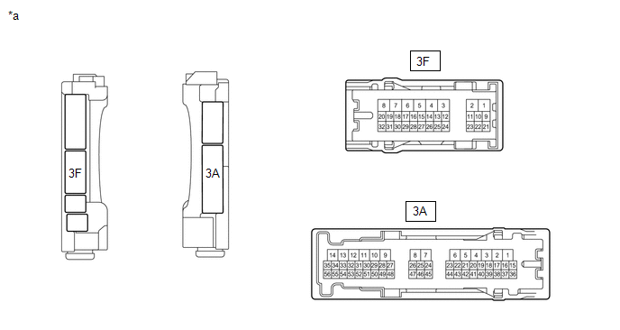
*a |
Component without harness connected (Instrument Panel Junction Block Assembly) |
- |
- |
(b) Measure the resistance according to the value(s) in the table below.
Standard Resistance:
|
Tester Connection |
Condition |
Specified Condition |
|---|---|---|
|
3F-5 - 3F-4 |
Battery voltage applied between terminals 3A-21 and 3A-18 |
Below 1 Ω |
|
Battery voltage not applied between terminals 3A-21 and 3A-18 |
10 kΩ or higher |
| NG | |
REPLACE INSTRUMENT PANEL JUNCTION BLOCK ASSEMBLY |
|
|
7. |
CHECK HARNESS AND CONNECTOR (INSTRUMENT PANEL JUNCTION BLOCK ASSEMBLY -WINDSHIELD GLASS (WINDSHIELD DEICER)) |
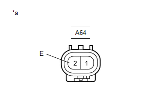
(a) Disconnect the A64 windshield glass (windshield deicer) connector.
(b) Disconnect the 3F instrument panel junction block.
(c) Measure the resistance according to the value(s) in the table below.
Standard resistance:
|
Tester Connection |
Condition |
Specified Condition |
|---|---|---|
|
3F-4 - A64-1 (B) |
Always |
Below 1 Ω |
|
3F-4 or A64-1 (B) - Body ground |
Always |
10 kΩ or higher |
| NG | |
REPAIR OR REPLACE HARNESS OR CONNECTOR |
|
|
8. |
CHECK HARNESS AND CONNECTOR (WINDSHIELD GLASS [WINDSHIELD DEICER] - BODY GROUND) |
|
(a) Disconnect the windshield glass (windshield deicer) connector. |
|
(b) Measure the resistance according to the value(s) in the table below.
Standard Resistance:
|
Tester Connection |
Condition |
Specified Condition |
|---|---|---|
|
A64-2 (E) - Body ground |
Always |
Below 1 Ω |
| OK | |
REPLACE WINDSHIELD GLASS (WINDSHIELD DEICER) |
| NG | |
REPAIR OR REPLACE HARNESS OR CONNECTOR |
 Data List / Active Test
DATA LIST / ACTIVE TEST
ACTIVE TEST
HINT:
Using the Techstream to perform Active Tests allows relays, VSVs, actuators and
other items to be operated without removing any parts. This non-intrusive ...
 Windshield Glass
...
Other materials:
Toyota CH-R Service Manual > Immobiliser System(w/o Smart Key System): Theft Deterrent System Communication Line High Fixation (B279A)
DESCRIPTION
If the communication line (EFIO-IMI) to the transponder key ECU assembly is stuck
high (e.g. shorted to +B), the ECM stores this DTC.
DTC No.
Detection Item
DTC Detection Condition
Trouble Area
Note
B279A
...
Toyota CH-R Service Manual > Vehicle Stability Control System: Open in ABS Solenoid Relay Circuit (C146E)
DESCRIPTION
The ABS solenoid relay is built into the skid control ECU in the brake actuator
assembly. The ABS solenoid relay supplies power to the ABS and TRAC solenoids. The
skid control ECU detects a solenoid relay malfunction by performing a self check
and relay operation check.
...
Toyota C-HR (AX20) 2023-2026 Owner's Manual
Toyota CH-R Owners Manual
- For safety and security
- Instrument cluster
- Operation of each component
- Driving
- Interior features
- Maintenance and care
- When trouble arises
- Vehicle specifications
- For owners
Toyota CH-R Service Manual
- Introduction
- Maintenance
- Audio / Video
- Cellular Communication
- Navigation / Multi Info Display
- Park Assist / Monitoring
- Brake (front)
- Brake (rear)
- Brake Control / Dynamic Control Systems
- Brake System (other)
- Parking Brake
- Axle And Differential
- Drive Shaft / Propeller Shaft
- K114 Cvt
- 3zr-fae Battery / Charging
- Networking
- Power Distribution
- Power Assist Systems
- Steering Column
- Steering Gear / Linkage
- Alignment / Handling Diagnosis
- Front Suspension
- Rear Suspension
- Tire / Wheel
- Tire Pressure Monitoring
- Door / Hatch
- Exterior Panels / Trim
- Horn
- Lighting (ext)
- Mirror (ext)
- Window / Glass
- Wiper / Washer
- Door Lock
- Heating / Air Conditioning
- Interior Panels / Trim
- Lighting (int)
- Meter / Gauge / Display
- Mirror (int)
- Power Outlets (int)
- Pre-collision
- Seat
- Seat Belt
- Supplemental Restraint Systems
- Theft Deterrent / Keyless Entry

0.0071