Toyota CH-R Service Manual: Adjustment
ADJUSTMENT
PROCEDURE
1. PREPARE VEHICLE FOR FOG LIGHT AIM ADJUSTMENT
(a) Prepare the vehicle:
- Ensure that there is no damage or deformation to the vehicle body around the fog lights.
- Fill the fuel tank.
- Make sure that the oil is filled to the specified level.
- Make sure that the engine coolant is filled to the specified level.
- Inflate the tires to the appropriate pressure.
- Unload the trunk and vehicle, ensuring that the spare tire, tools and jack are in their original positions.
- Bounce the vehicle at the corners up and down to stabilize the suspension.
- Sit a person of average weight (75 kg, 165 lb) in the driver's seat.
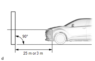
2. PREPARE FOR FOG LIGHT AIMING
|
(a) Prepare the vehicle:
NOTICE: A distance of 25 m (82 ft.) between the vehicle (fog light center mark) and the wall is necessary for proper aim adjustment. If sufficient space is not available, secure a distance of exactly 3 m (9.84 ft.) to allow for checking and adjustment of fog light aim. (The size of the target zone will change with the distance, so follow the instructions in the illustration.) |
|
(b) Prepare a piece of thick white paper (approximately 2 m (6.56 ft.) (height) x 4 m (13.1 ft.) (width)) to use as a screen.
(c) Draw a vertical line down the center of the screen (V line).
(d) Set the screen as shown in the illustration:
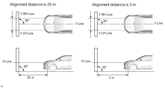
HINT:
- Stand the screen perpendicular to the ground.
- Align the V line on the screen with the center of the vehicle.
|
(e) Draw base lines (H, V LH, and V RH lines) on the screen as shown in the illustration. HINT: Mark the fog light center marks on the screen. (1) H Line (Fog light height): Draw a horizontal line across the screen so that it passes through the center marks. The H line should be at the same height as the fog light center marks. (2) V LH Line, V RH Line (Center mark position of left-hand (LH) and right-hand (RH) fog lights): Draw 2 vertical lines so that they intersect the H line at each center mark (aligned with the center mark of the fog lights). |
|
3. INSPECT FOG LIGHT AIMING
(a) Cover the fog light or disconnect the connector of the fog light on the opposite side to prevent light from the fog light that is not being inspected from affecting the fog light aiming inspection.
(b) Start the engine.
(c) Turn on the fog lights and check if the upper edge of the hot zone for each fog light matches the upper edge as shown in the illustration:
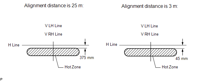
HINT:
- If the alignment distance is 25 m (82 ft.):
The upper edge of the hot zone for the fog light should be 249 mm (9.80 in.) below the H line.
- If the alignment distance is 3 m (9.84 ft.):
The upper edge of the hot zone for the fog light should be 30 mm (1.18 in.) below the H line.
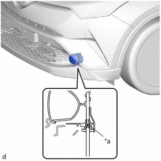
4. ADJUST FOG LIGHT AIMING
|
(a) Remove the 2 screws and clip and fold back part of the front fender liner. |
|
.png)
|
(b) Adjust the aim vertically: Adjust the aim of each fog light to the specified range by turning each aiming screw with a screwdriver. NOTICE: The final turn of the aiming screw should be made in the clockwise direction. If the screw is tightened excessively, loosen it and then retighten it, so that the final turn of the screw is in the clockwise direction. HINT: If it is not possible to correctly adjust the fog light aim, check the fog light assembly. |
|
 Disassembly
DISASSEMBLY
CAUTION / NOTICE / HINT
HINT:
Use the same procedure for the LH and RH sides.
The procedure described below is for the LH side.
PROCEDURE
1. REMOVE FOG LIGHT BULB
...
 Inspection
INSPECTION
PROCEDURE
1. INSPECT FOG LIGHT ASSEMBLY LH (for LED Type)
(a) Apply battery voltage to the fog light assembly LH and check that
the light comes on.
OK:
...
Other materials:
Toyota CH-R Service Manual > Immobiliser System(w/ Smart Key System): Security Indicator Light Does not Blink
DESCRIPTION
The certification ECU (smart key ECU assembly) blinks the security indicator
light (clock assembly) when the immobiliser is set (engine switch off).
WIRING DIAGRAM
CAUTION / NOTICE / HINT
NOTICE:
When using the Techstream with the engine switch off, connect the Techstrea ...
Toyota CH-R Service Manual > Smart Key System(for Start Function): Engine does not Start
DESCRIPTION
When the electrical key transmitter sub-assembly is in the cabin and the engine
switch is pressed, the certification ECU (smart key ECU assembly) receives a signal
and changes the power source mode. Additionally, when the shift lever is in P and
the brake pedal is depressed, the e ...
Toyota C-HR (AX20) 2023-2026 Owner's Manual
Toyota CH-R Owners Manual
- For safety and security
- Instrument cluster
- Operation of each component
- Driving
- Interior features
- Maintenance and care
- When trouble arises
- Vehicle specifications
- For owners
Toyota CH-R Service Manual
- Introduction
- Maintenance
- Audio / Video
- Cellular Communication
- Navigation / Multi Info Display
- Park Assist / Monitoring
- Brake (front)
- Brake (rear)
- Brake Control / Dynamic Control Systems
- Brake System (other)
- Parking Brake
- Axle And Differential
- Drive Shaft / Propeller Shaft
- K114 Cvt
- 3zr-fae Battery / Charging
- Networking
- Power Distribution
- Power Assist Systems
- Steering Column
- Steering Gear / Linkage
- Alignment / Handling Diagnosis
- Front Suspension
- Rear Suspension
- Tire / Wheel
- Tire Pressure Monitoring
- Door / Hatch
- Exterior Panels / Trim
- Horn
- Lighting (ext)
- Mirror (ext)
- Window / Glass
- Wiper / Washer
- Door Lock
- Heating / Air Conditioning
- Interior Panels / Trim
- Lighting (int)
- Meter / Gauge / Display
- Mirror (int)
- Power Outlets (int)
- Pre-collision
- Seat
- Seat Belt
- Supplemental Restraint Systems
- Theft Deterrent / Keyless Entry

0.0147