Toyota CH-R Service Manual: Back Door Entry Lock and Unlock Functions do not Operate
DESCRIPTION
If the entry lock and unlock functions do not operate for the back door only, the request code may not be being transmitted from the back door. If the entry functions for other doors operate properly, communication between the electrical key transmitter sub-assembly and electrical key and TPMS receiver assembly is normal. In this case, there may be a problem with request code transmission (communication between the certification ECU (smart key ECU assembly) and electrical key antenna (outside luggage compartment)) or there may be wave interference.
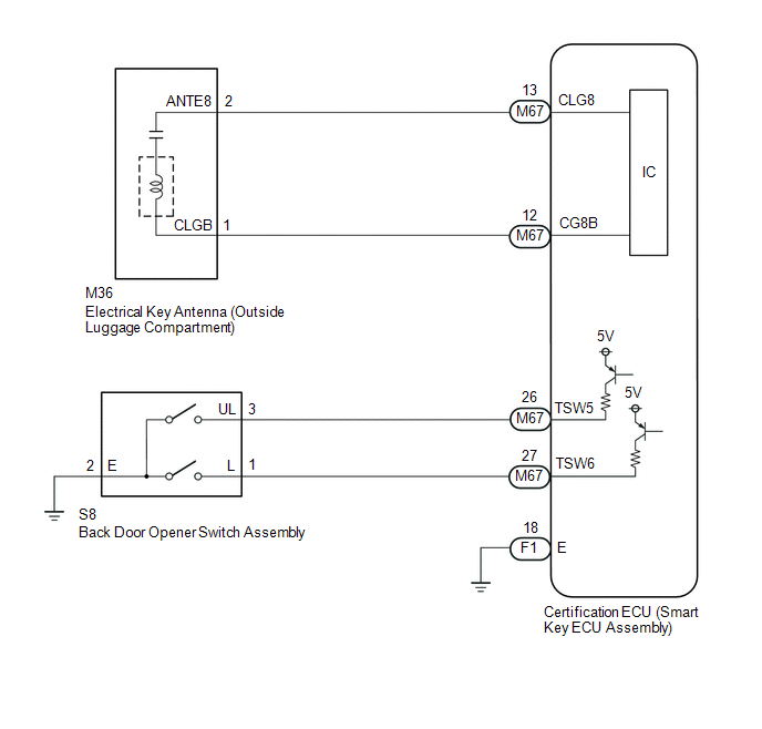
WIRING DIAGRAM
CAUTION / NOTICE / HINT
NOTICE:
- The smart key system (for Entry Function) uses the LIN communication
system and CAN communication system. Inspect the communication function
by following How to Proceed with Troubleshooting. Troubleshoot the smart
key system (for Entry Function) after confirming that the communication
systems are functioning properly.
Click here
.gif)
- When using the Techstream with the engine switch off, connect the Techstream to the DLC3 and turn a courtesy light switch on and off at intervals of 1.5 seconds or less until communication between the Techstream and the vehicle begins. Then select the vehicle type under manual mode and enter the following menus: Body Electrical / Smart Key. While using the Techstream, periodically turn a courtesy light switch on and off at intervals of 1.5 seconds or less to maintain communication between the Techstream and the vehicle.
- Check that there are no electrical key transmitter sub-assemblies in the vehicle.
- Before replacing the certification ECU (smart key ECU assembly), refer
to Precaution.
Click here
- After repair, confirm that no DTCs are output.
PROCEDURE
|
1. |
CHECK POWER DOOR LOCK CONTROL SYSTEM |
(a) When the door control switch on the multiplex network master switch assembly is operated, check that the doors unlock and lock according to the switch operation.
Click here
OK:
Door locks operate normally.
| NG | .gif) |
GO TO POWER DOOR LOCK CONTROL SYSTEM |
|
.gif)
|
2. |
CHECK FOR DTC |
(a) Check for DTCs.
Body Electrical > Smart Key > Trouble Codes|
Result |
Proceed to |
|---|---|
|
DTC B27A8 is not output |
A |
|
DTC B27A8 is output |
B |
| B | |
GO TO DIAGNOSTIC TROUBLE CODE CHART |
|
|
3. |
CHECK WAVE ENVIRONMENT |
|
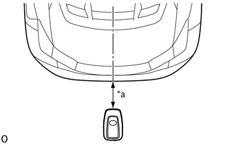
(a) Bring the electrical key transmitter sub-assembly approximately 0.7 to 1 m (2.30 to 3.28 ft.) from the electrical key antenna (outside luggage compartment) and perform an entry back door open/lock function check. Click here HINT:
|
|
|
Result |
Proceed to |
|---|---|
|
Entry function does not operate normally |
A |
|
Entry function operates normally |
B |
| B | |
AFFECTED BY WAVE INTERFERENCE |
|
|
4. |
READ VALUE USING TECHSTREAM (TR/B DOOR LOCK SW, TR/B DOOR UNLOCK SW) |
(a) Connect the Techstream to the DLC3.
(b) Turn the engine switch on (IG).
(c) Turn the Techstream on.
(d) Enter the following menus: Body Electrical / Smart Key / Data List.
(e) Read the Data List according to the display on the Techstream.
Body Electrical > Smart Key > Data List|
Tester Display |
Measurement Item |
Range |
Normal Condition |
Diagnostic Note |
|---|---|---|---|---|
|
Tr/B-Door Lock SW |
Back door opener switch assembly (lock switch) |
ON or OFF |
ON: Back door opener switch assembly (lock switch) pressed OFF: Back door opener switch assembly (lock switch) not pressed |
|
|
Tr/B-Door Unlock SW |
Back door opener switch assembly (open switch) |
ON or OFF |
ON: Back door opener switch assembly (open switch) pressed OFF: Back door opener switch assembly (open switch) not pressed |
|
|
Tester Display |
|---|
|
Tr/B-Door Lock SW |
|
Tr/B-Door Unlock SW |
OK:
The Techstream display changes correctly in response to the operation of the back door opener switch assembly.
| NG | |
GO TO STEP 9 |
|
|
5. |
CHECK KEY DIAGNOSTIC MODE |
(a) Check the following antenna in key diagnostic mode.
Body Electrical > Smart Key > Utility|
Tester Display |
|---|
|
Communication Check(Key Diag Mode) |
|
(b) Select either channel 1 or channel 2 and perform the key diagnostic mode inspection for each channel. (1) Check the electrical key antenna (outside luggage compartment): When the electrical key transmitter sub-assembly is brought within 0.7 to 1 m (2.30 to 3.28 ft.) of the electrical key antenna (outside luggage compartment), check that the wireless buzzer sounds. HINT:
|
|

|
Result |
Proceed to |
|---|---|
|
Wireless buzzer does not sound |
A |
|
Wireless buzzer sounds |
B |
| B | |
REPLACE CERTIFICATION ECU (SMART KEY ECU ASSEMBLY) |
|
|
6. |
CHECK HARNESS AND CONNECTOR (ELECTRICAL KEY ANTENNA (OUTSIDE LUGGAGE COMPARTMENT) - CERTIFICATION ECU (SMART KEY ECU ASSEMBLY)) |
(a) Disconnect the M67 certification ECU (smart key ECU assembly) connector.
(b) Disconnect the M36 electrical key antenna (outside luggage compartment) connector.
(c) Measure the resistance according to the value(s) in the table below.
Standard Resistance:
|
Tester Connection |
Condition |
Specified Condition |
|---|---|---|
|
M67-13 (CLG8) - M36-2 (ANTE8) |
Always |
Below 1 Ω |
|
M67-12 (CG8B) - M36-1 (CLGB) |
Always |
Below 1 Ω |
|
M67-13 (CLG8) or M36-2 (ANTE8) - Body ground |
Always |
10 kΩ or higher |
|
M67-12 (CG8B) or M36-1 (CLGB) - Body ground |
Always |
10 kΩ or higher |
(d) Reconnect the M36 electrical key antenna (outside luggage compartment) connector.
(e) Reconnect the M67 certification ECU (smart key ECU assembly) connector.
| NG | |
REPAIR OR REPLACE HARNESS OR CONNECTOR |
|
|
7. |
INSPECT CERTIFICATION ECU (SMART KEY ECU ASSEMBLY) (OUTPUT TO ELECTRICAL KEY ANTENNA (OUTSIDE LUGGAGE COMPARTMENT)) |
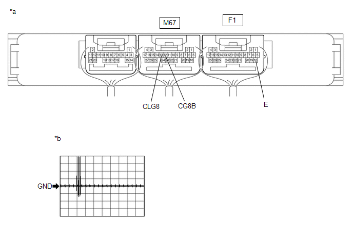
(a) Using an oscilloscope, check the waveform.
|
*a |
Component with harness connected (Certification ECU (Smart Key ECU Assembly)) |
*b |
Waveform 1 |
OK:
|
Tester Connection |
Condition |
Tool Setting |
Specified Condition |
|---|---|---|---|
|
M67-13 (CLG8) - F1-18(E) |
Procedure:
|
2 V/DIV., 500 ms/DIV. |
Pulse generation (See waveform 1) |
|
M67-12 (CG8B) - F1-18(E) |
Procedure:
|
2 V/DIV., 500 ms/DIV. |
Pulse generation (See waveform 1) |
| OK | |
REPLACE ELECTRICAL KEY ANTENNA (OUTSIDE LUGGAGE COMPARTMENT) |
|
|
8. |
CHECK ENTRY LOCK OPERATION |
(a) Connect all connectors and check that the function operates normally.
Click here
|
Result |
Proceed to |
|---|---|
|
Entry function does not operate normally |
A |
|
Entry function operates normally |
B |
| A | |
REPLACE CERTIFICATION ECU (SMART KEY ECU ASSEMBLY) |
| B | |
END (CONNECTOR WAS NOT CONNECTED SECURELY) |
|
9. |
CHECK HARNESS AND CONNECTOR (BACK DOOR OPENER SWITCH ASSEMBLY - CERTIFICATION ECU (SMART KEY ECU ASSEMBLY) AND BODY GROUND) |
(a) Disconnect the M67 certification ECU (smart key ECU assembly) connector.
(b) Disconnect the S8 back door opener switch assembly connector.
(c) Measure the resistance according to the value(s) in the table below.
Standard Resistance:
|
Tester Connection |
Condition |
Specified Condition |
|---|---|---|
|
M67-27 (TSW6) - S8-1 (L) |
Always |
Below 1 Ω |
|
M67-26 (TSW5) - S8-3 (UL) |
Always |
Below 1 Ω |
|
S8-2 (E) - Body ground |
Always |
Below 1 Ω |
|
M67-26 (TSW5) or S8-3 (UL) - Body ground |
Always |
10 kΩ or higher |
|
M67-27 (TSW6) or S8-1 (L) - Body ground |
Always |
10 kΩ or higher |
| NG | |
REPAIR OR REPLACE HARNESS OR CONNECTOR |
|
|
10. |
INSPECT BACK DOOR OPENER SWITCH ASSEMBLY |
(a) Remove the back door opener switch assembly.
Click here
(b) Inspect the back door opener switch assembly.
Click here
| NG | |
REPLACE BACK DOOR OPENER SWITCH ASSEMBLY |
|
|
11. |
CHECK ENTRY LOCK OPERATION |
(a) Connect all connectors and check that the function operates normally.
Click here
|
Result |
Proceed to |
|---|---|
|
Entry function does not operate normally |
A |
|
Entry function operates normally |
B |
| A | |
REPLACE CERTIFICATION ECU (SMART KEY ECU ASSEMBLY) |
| B | |
END (CONNECTOR WAS NOT CONNECTED SECURELY) |
 Entry Exterior Alarm does not Sound
DESCRIPTION
The smart key system (for Entry Function) uses the wireless door lock buzzer
to perform various vehicle exterior warnings. When the conditions of each warning
are met, the certificati ...
 Back Door Entry Lock Function does not Operate
DESCRIPTION
If the entry lock function does not operate for the back door only, but the entry
unlock function operates, the request code is being transmitted properly from the
back door. In this ...
Other materials:
Toyota CH-R Service Manual > Rear Door Speaker: Removal
REMOVAL
CAUTION / NOTICE / HINT
HINT:
Use the same procedure for the RH and LH sides.
The procedure listed below is for the LH side.
PROCEDURE
1. REMOVE REAR DOOR INSIDE HANDLE BEZEL PLUG
Click here
2. REMOVE REAR POWER WINDOW REGULATOR SWITCH ASSEMBLY WITH REAR DOOR ...
Toyota CH-R Service Manual > Automatic High Beam System: Automatic High Beam Camera (B124C)
DESCRIPTION
This DTC is stored when the main body ECU (multiplex network body ECU) detects
a malfunction in the forward recognition camera.
DTC No.
Detection Item
DTC Detection Condition
Trouble Area
B124C
Automatic High Bea ...
Toyota C-HR (AX20) 2023-2026 Owner's Manual
Toyota CH-R Owners Manual
- For safety and security
- Instrument cluster
- Operation of each component
- Driving
- Interior features
- Maintenance and care
- When trouble arises
- Vehicle specifications
- For owners
Toyota CH-R Service Manual
- Introduction
- Maintenance
- Audio / Video
- Cellular Communication
- Navigation / Multi Info Display
- Park Assist / Monitoring
- Brake (front)
- Brake (rear)
- Brake Control / Dynamic Control Systems
- Brake System (other)
- Parking Brake
- Axle And Differential
- Drive Shaft / Propeller Shaft
- K114 Cvt
- 3zr-fae Battery / Charging
- Networking
- Power Distribution
- Power Assist Systems
- Steering Column
- Steering Gear / Linkage
- Alignment / Handling Diagnosis
- Front Suspension
- Rear Suspension
- Tire / Wheel
- Tire Pressure Monitoring
- Door / Hatch
- Exterior Panels / Trim
- Horn
- Lighting (ext)
- Mirror (ext)
- Window / Glass
- Wiper / Washer
- Door Lock
- Heating / Air Conditioning
- Interior Panels / Trim
- Lighting (int)
- Meter / Gauge / Display
- Mirror (int)
- Power Outlets (int)
- Pre-collision
- Seat
- Seat Belt
- Supplemental Restraint Systems
- Theft Deterrent / Keyless Entry

0.0127