Toyota CH-R Service Manual: Back Door Entry Lock Function does not Operate
DESCRIPTION
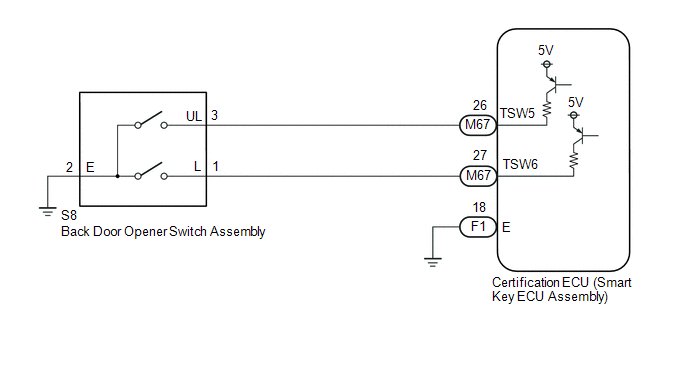
If the entry lock function does not operate for the back door only, but the entry unlock function operates, the request code is being transmitted properly from the back door. In this case, there may be a problem related to the lock switch (connection between the back door opener switch assembly and certification ECU (smart key ECU assembly)).
WIRING DIAGRAM
CAUTION / NOTICE / HINT
NOTICE:
- The smart key system (for Entry Function) uses the LIN communication
system and CAN communication system. Inspect the communication function
by following How to Proceed with Troubleshooting. Troubleshoot the smart
key system (for Entry Function) after confirming that the communication
systems are functioning properly.
Click here
.gif)
- When using the Techstream with the engine switch off, connect the Techstream to the DLC3 and turn a courtesy light switch on and off at intervals of 1.5 seconds or less until communication between the Techstream and the vehicle begins. Then select the vehicle type under manual mode and enter the following menus: Body Electrical / Smart Key. While using the Techstream, periodically turn a courtesy light switch on and off at intervals of 1.5 seconds or less to maintain communication between the Techstream and the vehicle.
- Check that there are no electrical key transmitter sub-assemblies in the vehicle.
- Before replacing the certification ECU (smart key ECU assembly), refer
to Precaution.
Click here
- After repair, confirm that no DTCs are output.
PROCEDURE
|
1. |
CHECK POWER DOOR LOCK CONTROL SYSTEM |
(a) When the door control switch on the multiplex network master switch assembly is operated, check that the doors unlock and lock according to the switch operation.
Click here
OK:
Door locks operate normally.
| NG | .gif) |
GO TO POWER DOOR LOCK CONTROL SYSTEM |
|
.gif)
|
2. |
INSPECT TECHSTREAM (TR/B-DOOR LOCK SW) |
(a) Connect the Techstream to the DLC3.
(b) Turn the engine switch on (IG).
(c) Turn the Techstream on.
(d) Enter the following menus: Body Electrical / Smart Key / Data List.
(e) Read the Data List according to the display on the Techstream.
Body Electrical > Smart Key > Data List|
Tester Display |
Measurement Item |
Range |
Normal Condition |
Diagnostic Note |
|---|---|---|---|---|
|
Tr/B-Door Lock SW |
Back door opener switch assembly (lock switch) |
ON or OFF |
ON: Back door opener switch assembly (lock switch) pressed OFF: Back door opener switch assembly (lock switch) not pressed |
|
|
Tester Display |
|---|
|
Tr/B-Door Lock SW |
HINT:
When checking the operation of the entry lock function several times, it can be operated up to 2 times consecutively. To operate the function 3 times or more consecutively, the doors need to be unlocked once. However, this is only for the entry lock function, other door lock operations, such as a wireless door lock operation can be performed consecutively.
OK:
The Techstream display changes correctly in response to the operation of the back door opener switch assembly.
| OK | |
REPLACE CERTIFICATION ECU (SMART KEY ECU ASSEMBLY) |
|
|
3. |
CHECK HARNESS AND CONNECTOR (BACK DOOR OPENER SWITCH ASSEMBLY - CERTIFICATION ECU (SMART KEY ECU ASSEMBLY)) |
(a) Disconnect the M67 certification ECU (smart key ECU assembly) connector.
(b) Disconnect the S8 back door opener switch assembly connector.
(c) Measure the resistance according to the value(s) in the table below.
Standard Resistance:
|
Tester Connection |
Condition |
Specified Condition |
|---|---|---|
|
M67-27 (TSW6) - S8-1 (L) |
Always |
Below 1 Ω |
|
S8-2 (E) - Body ground |
Always |
Below 1 Ω |
|
M67-27 (TSW6) or S8-1 (L) - Body ground |
Always |
10 kΩ or higher |
| NG | |
REPAIR OR REPLACE HARNESS OR CONNECTOR |
|
|
4. |
INSPECT BACK DOOR OPENER SWITCH ASSEMBLY (LOCK SWITCH) |
(a) Remove the back door opener switch assembly.
Click here
(b) Inspect the back door opener switch assembly.
Click here
| OK | |
REPLACE CERTIFICATION ECU (SMART KEY ECU ASSEMBLY) |
| NG | |
REPLACE BACK DOOR OPENER SWITCH ASSEMBLY |
 Back Door Entry Lock and Unlock Functions do not Operate
DESCRIPTION
If the entry lock and unlock functions do not operate for the back door only,
the request code may not be being transmitted from the back door. If the entry functions
for other doors ...
 Additional Key cannot be Registered
DESCRIPTION
If additional registration is not possible, a malfunction of the electrical key
transmitter sub-assembly, certification ECU (smart key ECU assembly), engine switch,
No. 1 indoor elect ...
Other materials:
Toyota CH-R Owners Manual > Driving: Refueling
Opening the fuel tank cap
Perform the following steps to open the fuel tank cap:
Before refueling the vehicle
Vehicles without a smart key system
Turn the engine switch to the "LOCK" position and ensure that all the doors
and windows are closed.
Vehicles with a smart key syste ...
Toyota CH-R Service Manual > Lighting System: Customize Parameters
CUSTOMIZE PARAMETERS
PROCEDURE
1. CUSTOMIZE LIGHTING SYSTEM (INT)
(a) Customizing using the Techstream
HINT:
The following items can be customized.
NOTICE:
When the customer requests a change in a function, first make sure that
the function can be customized.
Be sure to make a ...
Toyota C-HR (AX20) 2023-2026 Owner's Manual
Toyota CH-R Owners Manual
- For safety and security
- Instrument cluster
- Operation of each component
- Driving
- Interior features
- Maintenance and care
- When trouble arises
- Vehicle specifications
- For owners
Toyota CH-R Service Manual
- Introduction
- Maintenance
- Audio / Video
- Cellular Communication
- Navigation / Multi Info Display
- Park Assist / Monitoring
- Brake (front)
- Brake (rear)
- Brake Control / Dynamic Control Systems
- Brake System (other)
- Parking Brake
- Axle And Differential
- Drive Shaft / Propeller Shaft
- K114 Cvt
- 3zr-fae Battery / Charging
- Networking
- Power Distribution
- Power Assist Systems
- Steering Column
- Steering Gear / Linkage
- Alignment / Handling Diagnosis
- Front Suspension
- Rear Suspension
- Tire / Wheel
- Tire Pressure Monitoring
- Door / Hatch
- Exterior Panels / Trim
- Horn
- Lighting (ext)
- Mirror (ext)
- Window / Glass
- Wiper / Washer
- Door Lock
- Heating / Air Conditioning
- Interior Panels / Trim
- Lighting (int)
- Meter / Gauge / Display
- Mirror (int)
- Power Outlets (int)
- Pre-collision
- Seat
- Seat Belt
- Supplemental Restraint Systems
- Theft Deterrent / Keyless Entry

0.0148