Toyota CH-R Service Manual: Entry Exterior Alarm does not Sound
DESCRIPTION
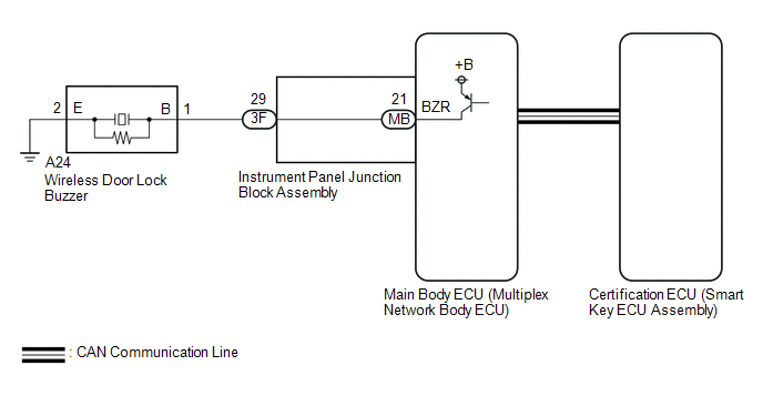
The smart key system (for Entry Function) uses the wireless door lock buzzer to perform various vehicle exterior warnings. When the conditions of each warning are met, the certification ECU (smart key ECU assembly) sends a buzzer activation request signal to the main body ECU (multiplex network body ECU) via CAN communication and the buzzer sounds.
WIRING DIAGRAM
CAUTION / NOTICE / HINT
NOTICE:
- The smart key system (for Entry Function) uses the LIN communication
system and CAN communication system. Inspect the communication function
by following How to Proceed with Troubleshooting. Troubleshoot the smart
key system (for Entry Function) after confirming that the communication
systems are functioning properly.
Click here
.gif)
- When using the Techstream with the engine switch off, connect the Techstream to the DLC3 and turn a courtesy light switch on and off at intervals of 1.5 seconds or less until communication between the Techstream and the vehicle begins. Then select the vehicle type under manual mode and enter the following menus: Body Electrical / Smart Key. While using the Techstream, periodically turn a courtesy light switch on and off at intervals of 1.5 seconds or less to maintain communication between the Techstream and the vehicle.
- Before replacing the certification ECU (smart key ECU assembly) or main
body ECU (multiplex network body ECU), refer to Precaution.
Click here
- After repair, confirm that no DTCs are output.
PROCEDURE
|
1. |
CHECK WIRELESS DOOR LOCK CONTROL SYSTEM |
(a) Check that the function operates normally.
Click here
|
Result |
Proceed to |
|---|---|
|
Wireless door lock function operates normally |
A |
|
Wireless door lock function does not operate normally |
B |
| B | .gif) |
GO TO PROBLEM SYMPTOMS TABLE |
|
.gif)
|
2. |
READ VALUE USING TECHSTREAM (EACH UNLOCK DETECTION SWITCH) |
(a) Connect the Techstream to the DLC3.
(b) Turn the engine switch on (IG).
(c) Turn the Techstream on.
(d) Enter the following menus: Body Electrical / Main Body / Data List.
(e) Read the Data List according to the display on the Techstream.
Body Electrical > Main Body > Data List|
Tester Display |
Measurement Item |
Range |
Normal Condition |
Diagnostic Note |
|---|---|---|---|---|
|
FR Door Lock Pos |
Front door RH unlock detection switch signal |
UNLOCK or LOCK |
UNLOCK: Front door RH unlocked LOCK: Front door RH locked |
- |
|
FL Door Lock Pos |
Front door LH unlock detection switch signal |
UNLOCK or LOCK |
UNLOCK: Front door LH unlocked LOCK: Front door LH locked |
- |
|
RR-Door Lock Pos SW |
Rear door LH and RH unlock detection switch signal |
ON or OFF |
ON: Rear door LH or rear door RH unlocked OFF: Rear door LH and rear door RH locked |
- |
|
RL-Door Lock Pos SW |
Rear door LH and RH unlock detection switch signal |
ON or OFF |
ON: Rear door LH or rear door RH unlocked OFF: Rear door LH and rear door RH locked |
- |
|
Tester Display |
|---|
|
FR Door Lock Pos |
|
FL Door Lock Pos |
|
RR-Door Lock Pos SW |
|
RL-Door Lock Pos SW |
OK:
The Techstream display changes correctly in response to the lock/unlock operation.
| NG | |
GO TO LIGHTING SYSTEM (Proceed to Door Unlock Detection Switch Circuit) |
|
|
3. |
PERFORM ACTIVE TEST USING TECHSTREAM (WIRELESS BUZZER) |
(a) Connect the Techstream to the DLC3.
(b) Turn the engine switch on (IG).
(c) Turn the Techstream on.
(d) Enter the following menus: Body Electrical / Main Body / Active Test.
(e) Perform Active Test according to the display on the Techstream.
Body Electrical > Main Body > Active Test|
Tester Display |
Measurement Item |
Control Range |
Diagnostic Note |
|---|---|---|---|
|
Wireless Buzzer |
Wireless door lock buzzer |
OFF/ON |
- |
|
Tester Display |
|---|
|
Wireless Buzzer |
|
Result |
Proceed to |
|---|---|
|
Wireless door lock buzzer does not sound |
A |
|
Wireless door lock buzzer sounds |
B |
| B | |
REPLACE CERTIFICATION ECU (SMART KEY ECU ASSEMBLY) |
|
|
4. |
CHECK WIRELESS DOOR LOCK BUZZER |
(a) Disconnect the A24 wireless door lock buzzer connector.
(b) Connect the Techstream to the DLC3.
(c) Turn the engine switch on (IG).
(d) Turn the Techstream on.
(e) Enter the following menus: Body Electrical / Main Body / Active Test.
(f) Perform Active Test according to the display on the Techstream.
Body Electrical > Main Body > Active Test|
Tester Display |
Measurement Item |
Control Range |
Diagnostic Note |
|---|---|---|---|
|
Wireless Buzzer |
Wireless door lock buzzer |
OFF/ON |
- |
|
Tester Display |
|---|
|
Wireless Buzzer |
|
(g) While performing the Active Test, measure the voltage between the terminals of the wireless door lock buzzer. Standard Voltage:
|
|
.png)
| OK | |
REPLACE WIRELESS DOOR LOCK BUZZER |
|
|
5. |
CHECK HARNESS AND CONNECTOR (WIRELESS DOOR LOCK BUZZER - MAIN BODY ECU (MULTIPLEX NETWORK BODY ECU) AND BODY GROUND) |
(a) Remove the main body ECU (multiplex network body ECU) from the instrument panel junction block assembly.
Click here
(b) Disconnect the A24 wireless door lock buzzer connector.
(c) Reconnect the 3F instrument panel junction block assembly connector.
(d) Measure the resistance according to the value(s) in the table below.
Standard Resistance:
|
Tester Connection |
Condition |
Specified Condition |
|---|---|---|
|
A24-1 (B) - MB-21 (BZR) |
Always |
Below 1 Ω |
|
A24-2 (E) - Body ground |
Always |
Below 1 Ω |
|
A24-1 (B) or MB-21 (BZR) - Body ground |
Always |
10 kΩ or higher |
| OK | |
REPLACE MAIN BODY ECU (MULTIPLEX NETWORK BODY ECU) |
|
|
6. |
CHECK HARNESS AND CONNECTOR (WIRELESS DOOR LOCK BUZZER - INSTRUMENT PANEL JUNCTION BLOCK ASSEMBLY) |
(a) Disconnect the 3F instrument panel junction block assembly connector.
(b) Disconnect the A24 wireless door lock buzzer connector.
(c) Measure the resistance according to the value(s) in the table below.
Standard Resistance:
|
Tester Connection |
Condition |
Specified Condition |
|---|---|---|
|
A24-1 (B) - 3F-29 |
Always |
Below 1 Ω |
|
A24-1 (B) or 3F-29 - Body ground |
Always |
10 kΩ or higher |
| OK | |
REPLACE INSTRUMENT PANEL JUNCTION BLOCK ASSEMBLY |
| NG | |
REPAIR OR REPLACE HARNESS OR CONNECTOR |
 Back Door Entry Unlock Function does not Operate
DESCRIPTION
If the entry unlock function does not operate for the back door only, but the
entry lock function operates, the request code is being transmitted properly from
the back door. In this ...
 Back Door Entry Lock and Unlock Functions do not Operate
DESCRIPTION
If the entry lock and unlock functions do not operate for the back door only,
the request code may not be being transmitted from the back door. If the entry functions
for other doors ...
Other materials:
Toyota CH-R Service Manual > Back Door: Adjustment
ADJUSTMENT
CAUTION / NOTICE / HINT
*a
Centering Bolt
*b
Standard Bolt
HINT:
Centering bolts are used to install the door hinges to the door. The
door cannot be adjusted with the centering bolts installed. Substitute the
...
Toyota CH-R Service Manual > Manual Headlight Beam Level Control System: How To Proceed With Troubleshooting
CAUTION / NOTICE / HINT
HINT:
Use the following procedure to troubleshoot the manual headlight beam level control
system.
PROCEDURE
1.
VEHICLE BROUGHT TO WORKSHOP
NEXT
2.
CU ...
Toyota C-HR (AX20) 2023-2026 Owner's Manual
Toyota CH-R Owners Manual
- For safety and security
- Instrument cluster
- Operation of each component
- Driving
- Interior features
- Maintenance and care
- When trouble arises
- Vehicle specifications
- For owners
Toyota CH-R Service Manual
- Introduction
- Maintenance
- Audio / Video
- Cellular Communication
- Navigation / Multi Info Display
- Park Assist / Monitoring
- Brake (front)
- Brake (rear)
- Brake Control / Dynamic Control Systems
- Brake System (other)
- Parking Brake
- Axle And Differential
- Drive Shaft / Propeller Shaft
- K114 Cvt
- 3zr-fae Battery / Charging
- Networking
- Power Distribution
- Power Assist Systems
- Steering Column
- Steering Gear / Linkage
- Alignment / Handling Diagnosis
- Front Suspension
- Rear Suspension
- Tire / Wheel
- Tire Pressure Monitoring
- Door / Hatch
- Exterior Panels / Trim
- Horn
- Lighting (ext)
- Mirror (ext)
- Window / Glass
- Wiper / Washer
- Door Lock
- Heating / Air Conditioning
- Interior Panels / Trim
- Lighting (int)
- Meter / Gauge / Display
- Mirror (int)
- Power Outlets (int)
- Pre-collision
- Seat
- Seat Belt
- Supplemental Restraint Systems
- Theft Deterrent / Keyless Entry

0.0078