Toyota CH-R Service Manual: Parts Location
PARTS LOCATION
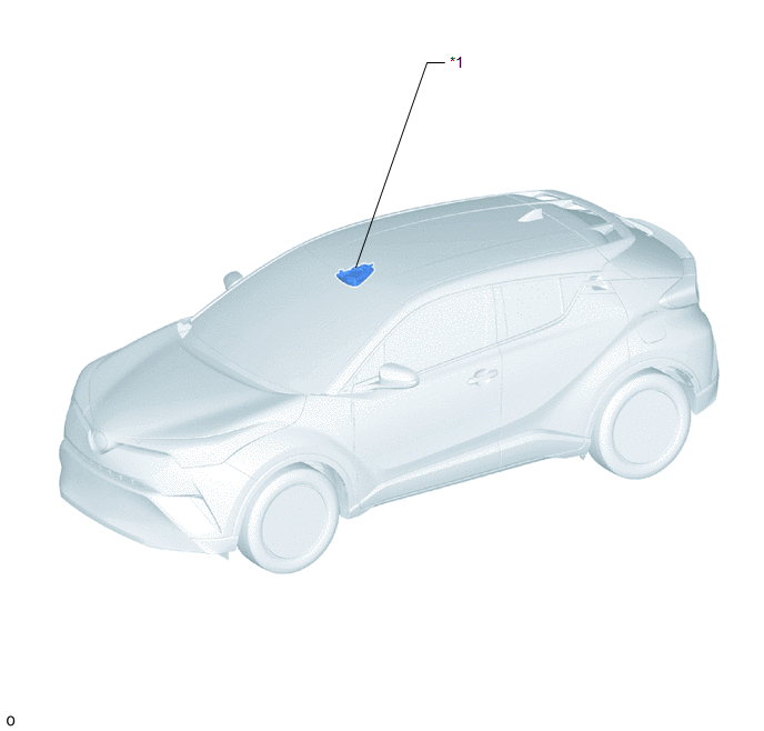
ILLUSTRATION
|
*1 |
MAP LIGHT ASSEMBLY (TELEPHONE MICROPHONE ASSEMBLY) |
- |
- |
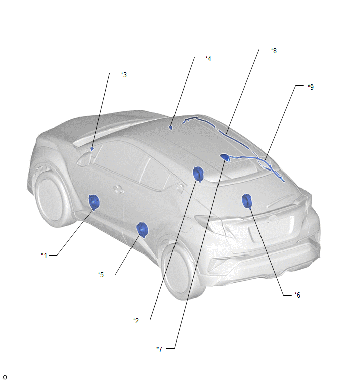
ILLUSTRATION
|
*1 |
FRONT NO. 1 SPEAKER ASSEMBLY LH |
*2 |
FRONT NO. 1 SPEAKER ASSEMBLY RH |
|
*3 |
FRONT NO. 2 SPEAKER ASSEMBLY LH |
*4 |
FRONT NO. 2 SPEAKER ASSEMBLY RH |
|
*5 |
REAR SPEAKER ASSEMBLY LH |
*6 |
REAR SPEAKER ASSEMBLY RH |
|
*7 |
ROOF ANTENNA ASSEMBLY |
*8 |
NO. 2 ANTENNA CORD SUB-ASSEMBLY |
|
*9 |
NO. 3 ANTENNA CORD SUB-ASSEMBLY |
- |
- |
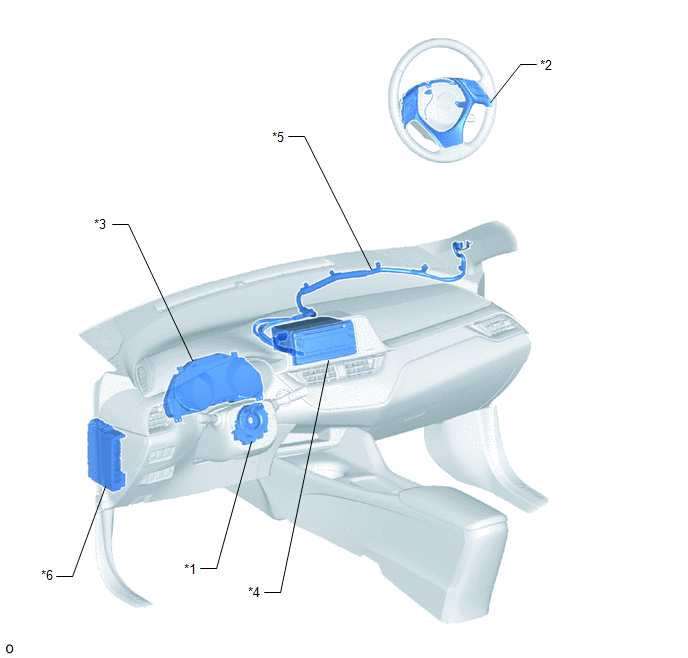
ILLUSTRATION
|
*1 |
SPIRAL CABLE WITH SENSOR SUB-ASSEMBLY |
*2 |
STEERING PAD SWITCH ASSEMBLY |
|
*3 |
COMBINATION METER ASSEMBLY |
*4 |
RADIO RECEIVER ASSEMBLY |
|
*5 |
ANTENNA CORD SUB-ASSEMBLY |
*6 |
INSTRUMENT PANEL JUNCTION BLOCK ASSEMBLY - RADIO FUSE - PANEL FUSE - ECU-ACC FUSE |
 Precaution
PRECAUTION
IGNITION SWITCH EXPRESSIONS
(a) The type of ignition switch used on this model differs depending on the specifications
of the vehicle. The expressions listed in the table below are used ...
 System Description
SYSTEM DESCRIPTION
CD (Compact Disc) PLAYER OUTLINE
(a) A compact disc player uses a laser pickup to read digital signals recorded
on a compact disc (CD). By converting the digital signals to anal ...
Other materials:
Toyota CH-R Service Manual > Rear Lower Arm: Components
COMPONENTS
ILLUSTRATION
*1
REAR COIL SPRING
*2
REAR LOWER COIL SPRING INSULATOR
*3
REAR NO. 2 SUSPENSION ARM ASSEMBLY
*4
REAR STABILIZER LINK ASSEMBLY
*5
REAR STABILIZER BAR
...
Toyota CH-R Service Manual > Ambient Light: Components
COMPONENTS
ILLUSTRATION
*A
for Driver Side
*B
for Front Passenger Side
*1
FRONT ARMREST BASE UPPER PANEL
*2
FRONT DOOR INSIDE HANDLE BEZEL PLUG
*3
FRONT DOOR TRIM BOARD SUB-A ...
Toyota C-HR (AX20) 2023-2026 Owner's Manual
Toyota CH-R Owners Manual
- For safety and security
- Instrument cluster
- Operation of each component
- Driving
- Interior features
- Maintenance and care
- When trouble arises
- Vehicle specifications
- For owners
Toyota CH-R Service Manual
- Introduction
- Maintenance
- Audio / Video
- Cellular Communication
- Navigation / Multi Info Display
- Park Assist / Monitoring
- Brake (front)
- Brake (rear)
- Brake Control / Dynamic Control Systems
- Brake System (other)
- Parking Brake
- Axle And Differential
- Drive Shaft / Propeller Shaft
- K114 Cvt
- 3zr-fae Battery / Charging
- Networking
- Power Distribution
- Power Assist Systems
- Steering Column
- Steering Gear / Linkage
- Alignment / Handling Diagnosis
- Front Suspension
- Rear Suspension
- Tire / Wheel
- Tire Pressure Monitoring
- Door / Hatch
- Exterior Panels / Trim
- Horn
- Lighting (ext)
- Mirror (ext)
- Window / Glass
- Wiper / Washer
- Door Lock
- Heating / Air Conditioning
- Interior Panels / Trim
- Lighting (int)
- Meter / Gauge / Display
- Mirror (int)
- Power Outlets (int)
- Pre-collision
- Seat
- Seat Belt
- Supplemental Restraint Systems
- Theft Deterrent / Keyless Entry

0.0103