Toyota CH-R Service Manual: Lost Communication with Meter (B1324)
DESCRIPTION
This DTC is stored when a communication error occurs between the radio and display receiver assembly and combination meter assembly.
|
DTC No. |
Detection Item |
DTC Detection Condition |
Trouble Area |
|---|---|---|---|
|
B1324 |
Lost Communication with Meter |
After the radio and display receiver assembly receives a registration information signal, which is sent by the combination meter assembly when the ignition switch is ON, 1 or more times, the radio and display receiver assembly does not receive the signal for 30 seconds or more |
|
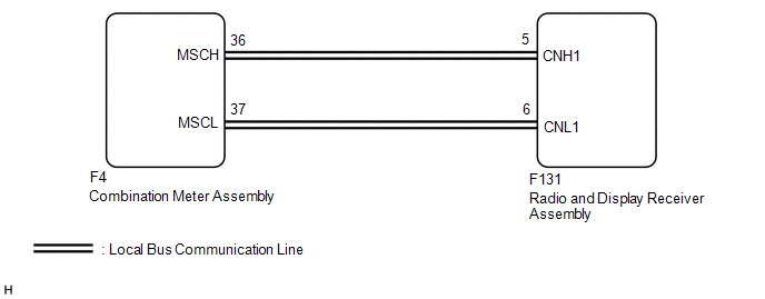
WIRING DIAGRAM
CAUTION / NOTICE / HINT
NOTICE:
- Depending on the parts that are replaced during vehicle inspection or
maintenance, performing initialization, registration or calibration may
be needed. Refer to Precaution for Audio and Visual System.
Click here
.gif)
- When replacing the radio and display receiver assembly, always replace
it with a new one. If a radio and display receiver assembly which was installed
to another vehicle is used, the following may occur:
- A communication malfunction DTC is stored.
- The radio and display receiver assembly or navigation ECU may not operate normally.
PROCEDURE
|
1. |
CHECK DTC (METER / GAUGE SYSTEM) |
(a) Clear the DTCs.
Body Electrical > Combination Meter > Trouble Codes(b) Recheck for DTCs and check that no DTCs are output.
Body Electrical > Combination Meter > Clear DTCsOK:
No DTCs are output.
| NG | .gif) |
GO TO METER / GAUGE SYSTEM |
|
.gif)
|
2. |
CHECK HARNESS AND CONNECTOR (RADIO AND DISPLAY RECEIVER ASSEMBLY - COMBINATION METER ASSEMBLY) |
(a) Disconnect the F131 radio and display receiver assembly connector.
(b) Disconnect the F4 combination meter assembly connector.
(c) Measure the resistance according to the value(s) in the table below.
Standard Resistance:
|
Tester Connection |
Condition |
Specified Condition |
|---|---|---|
|
F131-5 (CNH1) - F4-36 (MSCH) |
Always |
Below 1 Ω |
|
F131-6 (CNL1) - F4-37 (MSCL) |
Always |
Below 1 Ω |
|
F131-5 (CNH1) - Body ground |
Always |
10 kΩ or higher |
|
F131-6 (CNL1) - Body ground |
Always |
10 kΩ or higher |
| NG | |
REPAIR OR REPLACE HARNESS OR CONNECTOR |
|
|
3. |
REPLACE COMBINATION METER ASSEMBLY |
(a) Replace the combination meter assembly.
Click here
(b) Clear the DTCs.
Click here
(c) Recheck for DTCs and check that no DTCs are output.
Body Electrical > Combination Meter > Clear DTCsOK:
No DTCs are output.
| OK | |
END |
| NG | |
REPLACE RADIO AND DISPLAY RECEIVER ASSEMBLY |
 Voice Recognition Microphone Disconnected (B1579)
DESCRIPTION
The radio and display receiver assembly and map light assembly (telephone microphone
assembly) are connected to each other using the microphone connection detection
signal lines.
Thi ...
 HD Radio Tuner Malfunction (B1551,B158D,B15A0,B15B0,B15B3,B15B7,B15BA)
DESCRIPTION
These DTCs are stored when a malfunction occurs in the radio and display receiver
assembly.
DTC No.
Detection Item
DTC Detection Condition
T ...
Other materials:
Toyota CH-R Service Manual > Can Communication System: Open in Bus 3 Main Bus Line
DESCRIPTION
There may be an open circuit in one of the CAN main bus lines when the resistance
between terminals 6 (CA3H) and 21 (CA3L) of the central gateway ECU (network gateway
ECU) is 70 Ω or higher.
Symptom
Trouble Area
Resistance between terminals 6 ...
Toyota CH-R Service Manual > Front Seat Side Airbag Assembly: Removal
REMOVAL
CAUTION / NOTICE / HINT
The necessary procedures (adjustment, calibration, initialization, or registration)
that must be performed after parts are removed, installed, or replaced during the
front seat airbag assembly removal/installation are shown below.
Necessary Procedure After Part ...
Toyota C-HR (AX20) 2023-2026 Owner's Manual
Toyota CH-R Owners Manual
- For safety and security
- Instrument cluster
- Operation of each component
- Driving
- Interior features
- Maintenance and care
- When trouble arises
- Vehicle specifications
- For owners
Toyota CH-R Service Manual
- Introduction
- Maintenance
- Audio / Video
- Cellular Communication
- Navigation / Multi Info Display
- Park Assist / Monitoring
- Brake (front)
- Brake (rear)
- Brake Control / Dynamic Control Systems
- Brake System (other)
- Parking Brake
- Axle And Differential
- Drive Shaft / Propeller Shaft
- K114 Cvt
- 3zr-fae Battery / Charging
- Networking
- Power Distribution
- Power Assist Systems
- Steering Column
- Steering Gear / Linkage
- Alignment / Handling Diagnosis
- Front Suspension
- Rear Suspension
- Tire / Wheel
- Tire Pressure Monitoring
- Door / Hatch
- Exterior Panels / Trim
- Horn
- Lighting (ext)
- Mirror (ext)
- Window / Glass
- Wiper / Washer
- Door Lock
- Heating / Air Conditioning
- Interior Panels / Trim
- Lighting (int)
- Meter / Gauge / Display
- Mirror (int)
- Power Outlets (int)
- Pre-collision
- Seat
- Seat Belt
- Supplemental Restraint Systems
- Theft Deterrent / Keyless Entry

0.0103