Toyota CH-R Service Manual: XM Tuner Antenna Disconnected (B15FE,B15FF)
DESCRIPTION
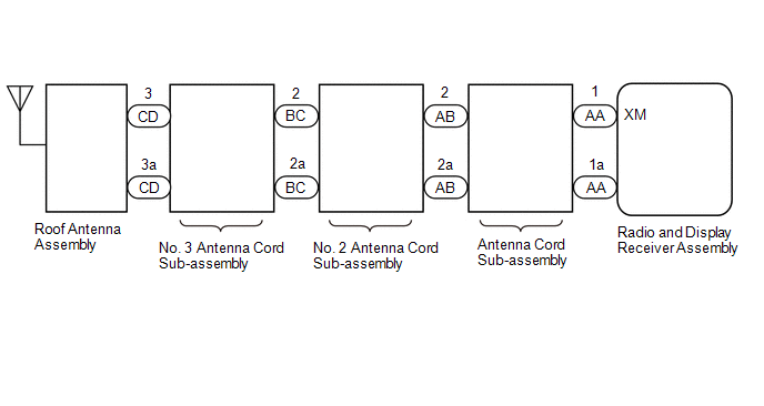
These DTCs are stored when a malfunction occurs in the roof antenna assembly which is connected to the radio and display receiver assembly.
|
DTC No. |
Detection Item |
DTC Detection Condition |
Trouble Area |
|---|---|---|---|
|
B15FE |
XM Tuner Antenna Disconnected |
The telephone antenna assembly is not connected |
|
|
B15FF |
XM Tuner Antenna Short |
A short occurs in the telephone antenna assembly |
|
WIRING DIAGRAM
for TMMT Made
for TMC Made

CAUTION / NOTICE / HINT
NOTICE:
- Depending on the parts that are replaced during vehicle inspection or
maintenance, performing initialization, registration or calibration may
be needed. Refer to Precaution for audio and visual system (for Radio and
Display Type).
Click here
.gif)
- When replacing the radio and display receiver assembly, always replace
it with a new one. If a radio and display receiver assembly which was installed
to another vehicle is used, the following may occur:
- A communication malfunction DTC is stored.
- The radio and display receiver assembly may not operate normally.
PROCEDURE
|
1. |
REPLACE ANTENNA CORD SUB-ASSEMBLY |
(a) Replace the antenna cord sub-assembly with a new or known good one.
Click here
(b) Clear the DTCs.
Body Electrical > Navigation System > Clear DTCs(c) Recheck for DTCs and check that no DTCs are output.
Body Electrical > Navigation System > Trouble CodesOK:
No DTCs are output.
|
Result |
Proceed to |
|---|---|
|
OK |
A |
|
NG (for TMMT Made) |
B |
|
NG (for TMC Made) |
C |
| A | .gif) |
END (ANTENNA CORD SUB-ASSEMBLY WAS DEFECTIVE) |
| C | |
GO TO STEP 5 |
|
.gif)
|
2. |
CHECK NO. 2 ANTENNA CORD SUB-ASSEMBLY |
|
(a) Disconnect the No. 2 antenna cord sub-assembly connector from the antenna cord sub-assembly. |
|
(b) Disconnect the No. 2 antenna cord sub-assembly connector from the No. 3 antenna cord sub-assembly.
(c) Measure the resistance according to the value(s) in the table below.
Standard Resistance:
|
Tester Connection |
Condition |
Specified Condition |
|---|---|---|
|
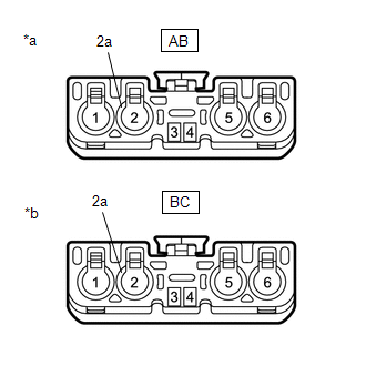
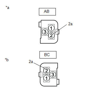
AB-2 - BC-2 |
Always |
Below 1 Ω |
|
AB-2a - BC-2a |
Always |
Below 1 Ω |
|
AB-2 - Body ground |
Always |
10 kΩ or higher |
|
AB-2a - Body ground |
Always |
10 kΩ or higher |
| NG | |
REPLACE NO. 2 ANTENNA CORD SUB-ASSEMBLY |
|
|
3. |
CHECK NO. 3 ANTENNA CORD SUB-ASSEMBLY |
|
(a) Disconnect the No. 3 antenna cord sub-assembly connector from the No. 2 antenna cord sub-assembly. |
|
(b) Disconnect the No. 3 antenna cord sub-assembly connector from the roof antenna assembly.
(c) Measure the resistance according to the value(s) in the table below.
Standard Resistance:
|
Tester Connection |
Condition |
Specified Condition |
|---|---|---|
|
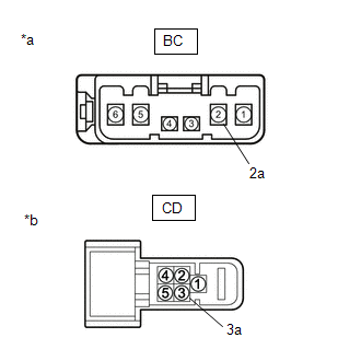
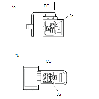
BC-2 - CD-3 |
Always |
Below 1 Ω |
|
BC-2a - CD-3a |
Always |
Below 1 Ω |
|
BC-2 - Body ground |
Always |
10 kΩ or higher |
|
BC-2a - Body ground |
Always |
10 kΩ or higher |
| NG | |
REPLACE NO. 3 ANTENNA CORD SUB-ASSEMBLY |
|
|
4. |
REPLACE ROOF ANTENNA ASSEMBLY |
(a) Replace the roof antenna assembly with a new or known good one.
Click here
(b) Clear the DTCs.
Body Electrical > Navigation System > Clear DTCs(c) Recheck for DTCs and check that no DTCs are output.
Body Electrical > Navigation System > Trouble CodesOK:
No DTCs are output.
| OK | |
END |
| NG | |
REPLACE RADIO AND DISPLAY RECEIVER ASSEMBLY |
|
5. |
CHECK NO. 2 ANTENNA CORD SUB-ASSEMBLY |
|
(a) Disconnect the No. 2 antenna cord sub-assembly connector from the antenna cord sub-assembly. |
|
(b) Disconnect the No. 2 antenna cord sub-assembly connector from the No. 3 antenna Cord sub-assembly.
(c) Measure the resistance according to the value(s) in the table below.
Standard Resistance:
|
Tester Connection |
Condition |
Specified Condition |
|---|---|---|
|
AB-2 - BC-2 |
Always |
Below 1 Ω |
|
AB-2a - BC-2a |
Always |
Below 1 Ω |
|
AB-2 - Body ground |
Always |
10 kΩ or higher |
|
AB-2a - Body ground |
Always |
10 kΩ or higher |
| NG | |
REPLACE NO. 2 ANTENNA CORD SUB-ASSEMBLY |
|
|
6. |
CHECK NO. 3 ANTENNA CORD SUB-ASSEMBLY |
|
(a) Disconnect the No. 3 antenna cord sub-assembly connector from the No. 2 antenna cord sub-assembly. |
|
(b) Disconnect the No. 3 antenna cord sub-assembly connector from the roof antenna assembly
(c) Measure the resistance according to the value(s) in the table below.
Standard Resistance:
|
Tester Connection |
Condition |
Specified Condition |
|---|---|---|
|
BC-2 - CD |
Always |
Below 1 Ω |
|
BC-2a - CD-3a |
Always |
Below 1 Ω |
|
BC-2 - Body ground |
Always |
10 kΩ or higher |
|
BC-2a - Body ground |
Always |
10 kΩ or higher |
| NG | |
REPLACE NO. 3 ANTENNA CORD SUB-ASSEMBLY |
|
|
7. |
REPLACE ROOF ANTENNA ASSEMBLY |
(a) Replace the roof antenna assembly with a new or known good one.
Click here
(b) Clear the DTCs.
Body Electrical > Navigation System > Clear DTCs(c) Recheck for DTCs and check that no DTCs are output.
Body Electrical > Navigation System > Trouble CodesOK:
No DTCs are output.
| OK | |
END |
| NG | |
REPLACE RADIO AND DISPLAY RECEIVER ASSEMBLY |
 Certification ECU Vehicle Information Reading/Writing Process Malfunction (B15F7)
DESCRIPTION
This DTC is stored when items controlled by the certification ECU (smart key
ECU assembly) cannot be customized via the audio and visual system vehicle customization
screen.
HINT:
T ...
 Main Body ECU Vehicle Information Reading/Writing Process Malfunction (B15F6)
DESCRIPTION
This DTC is stored when items controlled by the main body ECU (multiplex network
body ECU) cannot be customized via the audio and visual system vehicle customization
screen.
HINT:
T ...
Other materials:
Toyota CH-R Owners Manual > Steps to take in an emergency: If the electronic key does not operate properly (vehicles with a smart key system)
If communication between the electronic key and vehicle is interrupted
or the electronic key cannot be used because the battery is depleted, the smart
key system and wireless remote control cannot be used. In such cases, the doors
can be opened and the engine can be started by following the pr ...
Toyota CH-R Service Manual > Air Conditioning System(for Automatic Air Conditioning System With Side-mounted
Air Conditioner Pressure Sensor): Blower Motor Circuit
DESCRIPTION
The blower motor with fan sub-assembly is operated by signals from the air conditioning
amplifier assembly. Blower motor speed signals are transmitted in accordance with
changes in the duty ratio.
WIRING DIAGRAM
CAUTION / NOTICE / HINT
NOTICE:
Inspect the fuses for circuits re ...
Toyota C-HR (AX20) 2023-2026 Owner's Manual
Toyota CH-R Owners Manual
- For safety and security
- Instrument cluster
- Operation of each component
- Driving
- Interior features
- Maintenance and care
- When trouble arises
- Vehicle specifications
- For owners
Toyota CH-R Service Manual
- Introduction
- Maintenance
- Audio / Video
- Cellular Communication
- Navigation / Multi Info Display
- Park Assist / Monitoring
- Brake (front)
- Brake (rear)
- Brake Control / Dynamic Control Systems
- Brake System (other)
- Parking Brake
- Axle And Differential
- Drive Shaft / Propeller Shaft
- K114 Cvt
- 3zr-fae Battery / Charging
- Networking
- Power Distribution
- Power Assist Systems
- Steering Column
- Steering Gear / Linkage
- Alignment / Handling Diagnosis
- Front Suspension
- Rear Suspension
- Tire / Wheel
- Tire Pressure Monitoring
- Door / Hatch
- Exterior Panels / Trim
- Horn
- Lighting (ext)
- Mirror (ext)
- Window / Glass
- Wiper / Washer
- Door Lock
- Heating / Air Conditioning
- Interior Panels / Trim
- Lighting (int)
- Meter / Gauge / Display
- Mirror (int)
- Power Outlets (int)
- Pre-collision
- Seat
- Seat Belt
- Supplemental Restraint Systems
- Theft Deterrent / Keyless Entry

0.0086