Toyota CH-R Service Manual: No Response from ID BOX (B2789)
DESCRIPTION
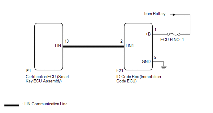
This DTC is stored when LIN communication between the certification ECU (smart key ECU assembly) and ID code box (immobiliser code ECU) stops for 10 seconds or more.
|
DTC No. |
Detection Item |
DTC Detection Condition |
Trouble Area |
|---|---|---|---|
|
B2789 |
No Response from ID BOX |
No communication between certification ECU (smart key ECU assembly) and ID code box (immobiliser code ECU) for 10 seconds or more. |
|
WIRING DIAGRAM
CAUTION / NOTICE / HINT
NOTICE:
- Inspect the fuses for circuits related to this system before performing the following procedure.
- When using the Techstream with the ignition switch off, connect the Techstream to the DLC3 and turn a courtesy light switch on and off at intervals of 1.5 seconds or less until communication between the Techstream and the vehicle begins. Then select the vehicle type under manual mode and enter the following menus: Body Electrical / Smart Key. While using the Techstream, periodically turn a courtesy light switch on and off at intervals of 1.5 seconds or less to maintain communication between the Techstream and the vehicle.
- If the certification ECU (smart key ECU assembly) or ID code box (immobiliser
code ECU) is replaced, refer to Registration.
Click here
.gif)
PROCEDURE
|
1. |
CHECK HARNESS AND CONNECTOR (CERTIFICATION ECU (SMART KEY ECU ASSEMBLY) - ID CODE BOX (IMMOBILISER CODE ECU)) |
(a) Disconnect the F1 certification ECU (smart key ECU assembly) connector.
(b) Disconnect the F21 ID code box (immobiliser code ECU) connector.
(c) Measure the resistance according to the value(s) in the table below.
NOTICE:
Make sure that each ECU is in sleep mode before performing the inspection. To enter sleep mode, turn the ignition switch from ON to off and wait for 180 seconds or more without operating any switches.
Standard Resistance:
|
Tester Connection |
Switch Condition |
Specified Condition |
|---|---|---|
|
F1-13 (LIN) - F21-2 (LIN1) |
Ignition switch off |
Below 1 Ω |
|
F1-13 (LIN) or F21-2 (LIN1) - Body ground |
Ignition switch off |
10 kΩ or higher |
| NG | .gif) |
REPAIR OR REPLACE HARNESS OR CONNECTOR |
|
.gif)
|
2. |
CHECK HARNESS AND CONNECTOR (ID CODE BOX (IMMOBILISER CODE ECU) - BATTERY, BODY GROUND) |
(a) Measure the voltage according to the value(s) in the table below.
Standard Voltage:
|
Tester Connection |
Condition |
Specified Condition |
|---|---|---|
|
F21-1 (+B) - F21-5 (GND) |
Always |
11 to 14 V |
(b) Measure the resistance according to the value(s) in the table below.
Standard Resistance:
|
Tester Connection |
Condition |
Specified Condition |
|---|---|---|
|
F21-5 (GND) - Body ground |
Always |
Below 1 Ω |
| NG | |
REPAIR OR REPLACE HARNESS OR CONNECTOR |
|
|
3. |
REPLACE ID CODE BOX (IMMOBILISER CODE ECU) |
(a) Replace the ID code box (immobiliser code ECU).
HINT:
Refer to Registration.
Click here
|
|
4. |
REGISTER ECU CODE REGISTRATION |
(a) Register the recognition codes in the ECUs.
HINT:
Refer to Registration.
Click here
|
|
5. |
CHECK FOR DTC |
(a) Clear the DTCs.
Click here
(b) Recheck for DTCs.
Body Electrical > Smart Key > Trouble CodesOK:
DTC B2789 is not output.
| OK | |
END (ID CODE BOX (IMMOBILISER CODE ECU) WAS DEFECTIVE) |
| NG | |
REPLACE CERTIFICATION ECU (SMART KEY ECU ASSEMBLY) |
 No Response from Steering Lock ECU (B2786)
DESCRIPTION
This DTC is stored when LIN communication between the certification ECU (smart
key ECU assembly) and steering lock ECU steering lock actuator or upper bracket
assembly) stops for 10 s ...
 Communication Malfunction between ECUs Connected by LIN (B2785)
DESCRIPTION
If the certification ECU (smart key ECU assembly) detects a communication error
with an ECU connected to the certification bus lines for 7 seconds or more, DTC
B2785 will be stored.
...
Other materials:
Toyota CH-R Service Manual > Vehicle Stability Control System: ABS does not Operate
DESCRIPTION
When the vehicle stability control system is operating, as the input piston and
output piston are not directly connected, the kickback of the brake pedal is minimal
during ABS operation and the driver may not notice that ABS operated.
CAUTION / NOTICE / HINT
NOTICE:
When replacin ...
Toyota CH-R Service Manual > Navigation System: Registered Device cannot be Deleted
PROCEDURE
1.
DELETE OPERATION
(a) Check if a registered portable player can be deleted normally.
OK:
Registered portable player can be deleted normally.
OK
END
NG
PROCEED TO NEXT SUSPECTED AREA SHOWN IN PROBLEM SYM ...
Toyota C-HR (AX20) 2023-2026 Owner's Manual
Toyota CH-R Owners Manual
- For safety and security
- Instrument cluster
- Operation of each component
- Driving
- Interior features
- Maintenance and care
- When trouble arises
- Vehicle specifications
- For owners
Toyota CH-R Service Manual
- Introduction
- Maintenance
- Audio / Video
- Cellular Communication
- Navigation / Multi Info Display
- Park Assist / Monitoring
- Brake (front)
- Brake (rear)
- Brake Control / Dynamic Control Systems
- Brake System (other)
- Parking Brake
- Axle And Differential
- Drive Shaft / Propeller Shaft
- K114 Cvt
- 3zr-fae Battery / Charging
- Networking
- Power Distribution
- Power Assist Systems
- Steering Column
- Steering Gear / Linkage
- Alignment / Handling Diagnosis
- Front Suspension
- Rear Suspension
- Tire / Wheel
- Tire Pressure Monitoring
- Door / Hatch
- Exterior Panels / Trim
- Horn
- Lighting (ext)
- Mirror (ext)
- Window / Glass
- Wiper / Washer
- Door Lock
- Heating / Air Conditioning
- Interior Panels / Trim
- Lighting (int)
- Meter / Gauge / Display
- Mirror (int)
- Power Outlets (int)
- Pre-collision
- Seat
- Seat Belt
- Supplemental Restraint Systems
- Theft Deterrent / Keyless Entry

0.0087