Toyota CH-R Service Manual: Communication Malfunction between ECUs Connected by LIN (B2785)
DESCRIPTION
If the certification ECU (smart key ECU assembly) detects a communication error with an ECU connected to the certification bus lines for 7 seconds or more, DTC B2785 will be stored.
|
DTC No. |
Detection Item |
DTC Detection Condition |
Trouble Area |
|---|---|---|---|
|
B2785 |
Communication Malfunction between ECUs Connected by LIN |
Any of the following conditions is met:
|
|
|
Vehicle Condition |
|||||
|---|---|---|---|---|---|
|
Pattern 1 |
Pattern 2 |
Pattern 3 |
Pattern 4 |
||
|
Diagnosis Condition |
- |
○ |
○ |
○ |
○ |
|
Malfunction Status |
Errors in LIN communication between ECUs |
○ |
- |
- |
- |
|
Open in communication lines |
- |
○ |
- |
- |
|
|
Short in communication lines |
- |
- |
○ |
- |
|
|
The certification ECU (smart key ECU assembly) detects a communication error with an ECU connected to the certification bus lines |
- |
- |
- |
○ |
|
|
Detection Time |
- |
- |
- |
7 seconds or more |
|
|
Number of Trips |
1 trip |
1 trip |
1 trip |
1 trip |
|
HINT:
DTC will be output when conditions for either of the patterns in the table above are met.
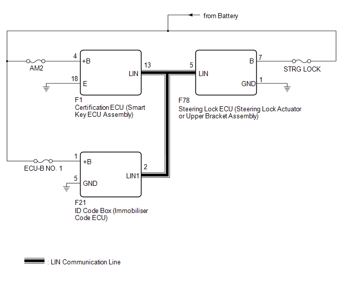
WIRING DIAGRAM
CAUTION / NOTICE / HINT
NOTICE:
- Inspect the fuses for circuits related to this system before performing the following procedure.
- Before performing the inspection, check that DTC B2786, B2789 or B278C
is not output.
Click here
.gif)
- When using the Techstream with the ignition switch off, connect the Techstream to the DLC3 and turn a courtesy light switch on and off at intervals of 1.5 seconds or less until communication between the Techstream and the vehicle begins. Then select the vehicle type under manual mode and enter the following menus: Body Electrical / Smart Key. While using the Techstream, periodically turn a courtesy light switch on and off at intervals of 1.5 seconds or less to maintain communication between the Techstream and the vehicle.
- If the certification ECU (smart key ECU assembly), ID code box (immobiliser
code ECU) and steering lock ECU (steering lock actuator or upper bracket
assembly) is replaced, refer to Registration.
Click here
PROCEDURE
|
1. |
CHECK HARNESS AND CONNECTOR (CERTIFICATION ECU (SMART KEY ECU ASSEMBLY) - EACH ECU) |
(a) Disconnect the F1 certification ECU (smart key ECU assembly) connector.
(b) Disconnect the F78 steering lock ECU (steering lock actuator or upper bracket assembly) connector.
(c) Disconnect the F21 ID code box (immobiliser code ECU) connector.
(d) Measure the resistance according to the value(s) in the table below.
NOTICE:
Make sure that each ECU is in sleep mode before performing the inspection. To enter sleep mode, turn the ignition switch from ON to off and wait for 180 seconds or more without operating any switches.
Standard Resistance:
|
Tester Connection |
Switch Condition |
Specified Condition |
|---|---|---|
|
F1-13 (LIN) - F21-2 (LIN1) |
Ignition switch off |
Below 1 Ω |
|
F1-13 (LIN) - F78-5 (LIN) |
Ignition switch off |
Below 1 Ω |
|
F1-13 (LIN), F78-5 (LIN) or F21-2 (LIN1) - Body ground |
Ignition switch off |
10 kΩ or higher |
| NG | .gif) |
REPAIR OR REPLACE HARNESS OR CONNECTOR |
|
.gif)
|
2. |
CHECK FOR DTC (STEERING LOCK ECU (STEERING LOCK ACTUATOR OR UPR BRACKET ASSEMBLY)) |
(a) Reconnect the F1 certification ECU (smart key ECU assembly) connector.
(b) Reconnect the F21 ID code box (immobiliser code ECU) connector.
(c) Clear the DTCs.
Click here
(d) Recheck for DTCs.
Body Electrical > Smart Key > Trouble Codes|
Result |
Proceed to |
|---|---|
|
DTC B2785 is output |
A |
|
DTC B2785 is not output |
B |
| B | |
REPLACE STEERING LOCK ECU (STEERING LOCK ACTUATOR OR UPPER BRACKET ASSEMBLY) |
|
|
3. |
CHECK FOR DTC (ID CODE BOX (IMMOBILISER CODE ECU)) |
(a) Reconnect the F78 steering lock ECU (steering lock actuator or upper bracket assembly) connector.
(b) Disconnect the F21 ID code box (immobiliser code ECU) connector.
(c) Clear the DTCs.
Click here
(d) Recheck for DTCs.
Body Electrical > Smart Key > Trouble Codes|
Result |
Proceed to |
|---|---|
|
DTC B2785 is output |
A |
|
DTC B2785 is not output |
B |
| A | |
REPLACE CERTIFICATION ECU (SMART KEY ECU ASSEMBLY) |
| B | |
REPLACE ID CODE BOX (IMMOBILISER CODE ECU)
|
 No Response from ID BOX (B2789)
DESCRIPTION
This DTC is stored when LIN communication between the certification ECU (smart
key ECU assembly) and ID code box (immobiliser code ECU) stops for 10 seconds or
more.
DTC N ...
 P/W Master Switch Communication Stop (B1206)
DESCRIPTION
This DTC is stored when LIN communication between the multiplex network master
switch assembly and main body ECU (multiplex network body ECU) stops for 10 seconds
or more.
...
Other materials:
Toyota CH-R Service Manual > Transmission Control Cable: Adjustment
ADJUSTMENT
PROCEDURE
1. SECURE VEHICLE
(a) Fully apply the parking brake and chock a wheel.
CAUTION:
Make sure to apply the parking brake and chock a wheel before performing
this procedure.
If the vehicle is not secure and the shift lever is moved to N, the
vehicle may sudd ...
Toyota CH-R Service Manual > Rear Seat Outer Belt Assembly: Components
COMPONENTS
ILLUSTRATION
*A
w/ Package Tray Trim
*B
w/ Tonneau Cover
*1
PACKAGE TRAY TRIM PANEL ASSEMBLY
*2
TONNEAU COVER ASSEMBLY
ILLUSTRATION
*A
for Type A
...
Toyota C-HR (AX20) 2023-2026 Owner's Manual
Toyota CH-R Owners Manual
- For safety and security
- Instrument cluster
- Operation of each component
- Driving
- Interior features
- Maintenance and care
- When trouble arises
- Vehicle specifications
- For owners
Toyota CH-R Service Manual
- Introduction
- Maintenance
- Audio / Video
- Cellular Communication
- Navigation / Multi Info Display
- Park Assist / Monitoring
- Brake (front)
- Brake (rear)
- Brake Control / Dynamic Control Systems
- Brake System (other)
- Parking Brake
- Axle And Differential
- Drive Shaft / Propeller Shaft
- K114 Cvt
- 3zr-fae Battery / Charging
- Networking
- Power Distribution
- Power Assist Systems
- Steering Column
- Steering Gear / Linkage
- Alignment / Handling Diagnosis
- Front Suspension
- Rear Suspension
- Tire / Wheel
- Tire Pressure Monitoring
- Door / Hatch
- Exterior Panels / Trim
- Horn
- Lighting (ext)
- Mirror (ext)
- Window / Glass
- Wiper / Washer
- Door Lock
- Heating / Air Conditioning
- Interior Panels / Trim
- Lighting (int)
- Meter / Gauge / Display
- Mirror (int)
- Power Outlets (int)
- Pre-collision
- Seat
- Seat Belt
- Supplemental Restraint Systems
- Theft Deterrent / Keyless Entry

0.0078