Toyota CH-R Service Manual: No Response from Steering Lock ECU (B2786)
DESCRIPTION
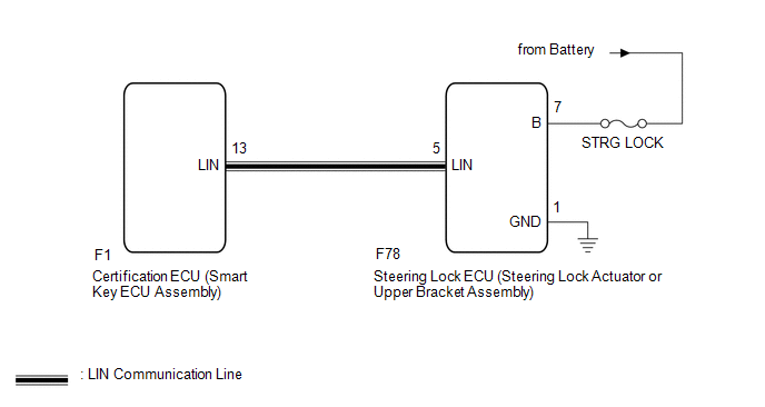
This DTC is stored when LIN communication between the certification ECU (smart key ECU assembly) and steering lock ECU steering lock actuator or upper bracket assembly) stops for 10 seconds or more.
|
DTC No. |
Detection Item |
DTC Detection Condition |
Trouble Area |
|---|---|---|---|
|
B2786 |
No Response from Steering Lock ECU |
No communication between steering lock ECU (steering lock actuator or upper bracket assembly) and certification ECU (smart key ECU assembly) for 10 seconds or more. |
|
WIRING DIAGRAM
CAUTION / NOTICE / HINT
NOTICE:
- Inspect the fuses for circuits related to this system before performing the following procedure.
- When using the Techstream with the ignition switch off, connect the Techstream to the DLC3 and turn a courtesy light switch on and off at intervals of 1.5 seconds or less until communication between the Techstream and the vehicle begins. Then select the vehicle type under manual mode and enter the following menus: Body Electrical / Smart Key. While using the Techstream, periodically turn a courtesy light switch on and off at intervals of 1.5 seconds or less to maintain communication between the Techstream and the vehicle.
- If the certification ECU (smart key ECU assembly) or steering lock ECU
(steering lock actuator or upper bracket assembly) is replaced, refer to
Registration.
Click here
.gif)
PROCEDURE
|
1. |
CHECK HARNESS AND CONNECTOR (CERTIFICATION ECU (SMART KEY ECU ASSEMBLY) - STEERING LOCK ECU (STEERING LOCK ACTUATOR OR UPPER BRACKET ASSEMBLY)) |
(a) Disconnect the F1 certification ECU (smart key ECU assembly) connector.
(b) Disconnect the F78 steering lock ECU (steering lock actuator or upper bracket assembly) connector.
(c) Measure the resistance according to the value(s) in the table below.
NOTICE:
Make sure that each ECU is in sleep mode before performing the inspection. To enter sleep mode, turn the ignition switch from ON to off and wait for 180 seconds or more without operating any switches.
Standard Resistance:
|
Tester Connection |
Switch Condition |
Specified Condition |
|---|---|---|
|
F1-13 (LIN) - F78-5 (LIN) |
Ignition switch off |
Below 1 Ω |
|
F1-13 (LIN) or F78-5 (LIN) - Body ground |
Ignition switch off |
10 kΩ or higher |
| NG | .gif) |
REPAIR OR REPLACE HARNESS OR CONNECTOR |
|
.gif)
|
2. |
CHECK HARNESS AND CONNECTOR (STEERING LOCK ECU (STEERING LOCK ACTUATOR OR UPPER BRACKET ASSEMBLY) - BATTERY, BODY GROUND) |
(a) Measure the voltage according to the value(s) in the table below.
Standard Voltage:
|
Tester Connection |
Condition |
Specified Condition |
|---|---|---|
|
F78-7 (B) - F78-1 (GND) |
Always |
11 to 14 V |
(b) Measure the resistance according to the value(s) in the table below.
Standard Resistance:
|
Tester Connection |
Condition |
Specified Condition |
|---|---|---|
|
F78-1 (GND) - Body ground |
Always |
Below 1 Ω |
| NG | |
REPAIR OR REPLACE HARNESS OR CONNECTOR |
|
|
3. |
REPLACE STEERING LOCK ECU (STEERING LOCK ACTUATOR OR UPPER BRACKET ASSEMBLY) |
(a) Replace the steering lock ECU (steering lock actuator or upper bracket assembly).
Click here
|
|
4. |
REGISTER ECU CODE REGISTRATION |
(a) Register the recognition codes in the ECUs.
HINT:
Refer to Registration.
Click here
|
|
5. |
CHECK FOR DTC |
(a) Clear the DTCs.
Click here
(b) Recheck for DTCs.
Body Electrical > Smart Key > Trouble CodesOK:
DTC B2786 is not output.
| OK | |
END (STEERING LOCK ECU (STEERING LOCK ACTUATOR OR UPPER BRACKET ASSEMBLY) WAS DEFECTIVE) |
| NG | |
REPLACE CERTIFICATION ECU (SMART KEY ECU ASSEMBLY) |
 Diagnostic Trouble Code Chart
DIAGNOSTIC TROUBLE CODE CHART
LIN Communication System
DTC No.
Detection Item
Link
B1206
P/W Master Switch Communication Stop
...
 No Response from ID BOX (B2789)
DESCRIPTION
This DTC is stored when LIN communication between the certification ECU (smart
key ECU assembly) and ID code box (immobiliser code ECU) stops for 10 seconds or
more.
DTC N ...
Other materials:
Toyota CH-R Service Manual > Can Communication System: Check Bus 1 Lines for Short Circuit
DESCRIPTION
There may be a short circuit between the CAN main bus lines and/or CAN branch
lines when the resistance between terminals 23 (CA1H) and 8 (CA1L) of the central
gateway ECU (network gateway ECU) is below 54 Ω.
Symptom
Trouble Area
Resistance b ...
Toyota CH-R Service Manual > Front Door Belt Moulding: Installation
INSTALLATION
CAUTION / NOTICE / HINT
HINT:
Use the same procedure for the RH side and LH side.
The following procedure is for the LH side.
PROCEDURE
1. INSTALL FRONT DOOR BELT MOULDING ASSEMBLY
Install in this Direction
(a) Engage the claws to ...
Toyota C-HR (AX20) 2023-2026 Owner's Manual
Toyota CH-R Owners Manual
- For safety and security
- Instrument cluster
- Operation of each component
- Driving
- Interior features
- Maintenance and care
- When trouble arises
- Vehicle specifications
- For owners
Toyota CH-R Service Manual
- Introduction
- Maintenance
- Audio / Video
- Cellular Communication
- Navigation / Multi Info Display
- Park Assist / Monitoring
- Brake (front)
- Brake (rear)
- Brake Control / Dynamic Control Systems
- Brake System (other)
- Parking Brake
- Axle And Differential
- Drive Shaft / Propeller Shaft
- K114 Cvt
- 3zr-fae Battery / Charging
- Networking
- Power Distribution
- Power Assist Systems
- Steering Column
- Steering Gear / Linkage
- Alignment / Handling Diagnosis
- Front Suspension
- Rear Suspension
- Tire / Wheel
- Tire Pressure Monitoring
- Door / Hatch
- Exterior Panels / Trim
- Horn
- Lighting (ext)
- Mirror (ext)
- Window / Glass
- Wiper / Washer
- Door Lock
- Heating / Air Conditioning
- Interior Panels / Trim
- Lighting (int)
- Meter / Gauge / Display
- Mirror (int)
- Power Outlets (int)
- Pre-collision
- Seat
- Seat Belt
- Supplemental Restraint Systems
- Theft Deterrent / Keyless Entry

0.0073