Toyota CH-R Service Manual: Terminals Of Ecm
TERMINALS OF ECM
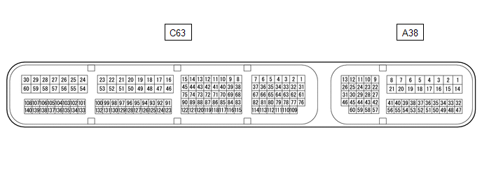
ECM
HINT:
The standard voltage and resistance of each ECM terminal is shown in the table below.
In the table, first follow the information under "Condition". Look under "Terminal No. (Symbol)" for the terminals to be inspected. The standard voltage or resistance between the terminals is shown under "Specified Condition".
Use the illustration above as a reference for the ECM terminals.
|
Terminal No. (Symbol) |
Wiring Color |
Terminal Description |
Condition |
Specified Condition |
|---|---|---|---|---|
|
A38-1 (BATT) - C63-59 (E1) |
R - W-B |
Battery (for measuring battery voltage and for ECM memory) |
Always |
11 to 14 V |
|
A38-2 (+B) - C63-59 (E1) |
B - W-B |
Power source of ECM |
Ignition switch ON |
11 to 14 V |
|
A38-3 (+B2) - C63-59 (E1) |
B - W-B |
Power source of ECM |
Ignition switch ON |
11 to 14 V |
|
A38-9 (STP) - C63-59 (E1) |
R - W-B |
Stop light switch assembly signal |
Brake pedal depressed |
7.5 to 14 V |
|
Brake pedal released |
Below 1.5 V |
|||
|
A38-13 (CANH) - C63-59 (E1) |
R - W-B |
CAN communication line |
Ignition switch ON |
Pulse generation |
|
A38-23 (NSW) - C63-59 (E1) |
W - W-B |
Park/neutral position switch signal |
Ignition switch ON and shift lever in P or N |
Below 1 V |
|
Ignition switch ON and shift lever not in P or N |
11 to 14 V |
|||
|
A38-26 (CANL) - C63-59 (E1) |
P - W-B |
CAN communication line |
Ignition switch ON |
Pulse generation |
|
A38-42 (SFTU) - C63-59 (E1) |
B - W-B |
Up-shift position switch signal |
Ignition switch ON and shift lever in M |
11 to 14 V |
|
Ignition switch ON and shift lever in "+" |
Below 1 V |
|||
|
A38-43 (SFTD) - C63-59 (E1) |
SB - W-B |
Down-shift position switch signal |
Ignition switch ON and shift lever in M |
11 to 14 V |
|
Ignition switch ON and shift lever in "-" |
Below 1 V |
|||
|
A38-46 (MREL) - C63-59 (E1) |
G - W-B |
EFI-MAIN NO. 1 relay |
Ignition switch ON |
11 to 14 V |
|
A38-59 (S) - C63-59 (E1) |
W - W-B |
M position switch signal |
Ignition switch ON and shift lever in M, "+" or "-" |
11 to 14 V |
|
Ignition switch ON and shift lever not in M, "+" or "-" |
Below 1 V |
|||
|
C63-29 (+BM) - C63-59 (E1) |
P - W-B |
Power source of throttle actuator |
Always |
11 to 14 V |
|
C63-39 (SLP+) - C63-38 (SLP-) |
LG - R |
Shift solenoid valve SLP signal |
Engine idling |
Pulse generation |
|
C63-41 (SC) - C63-59 (E1) |
W - W-B |
Shift solenoid valve SC signal |
|
Pulse generation |
|
C63-43 (SLU+) - C63-42 (SLU-) |
BR - LG |
Shift solenoid valve SLU signal |
Lock-up turned from OFF to ON |
Pulse generation |
|
C63-45 (SLS+) - C63-44 (SLS-) |
B - L |
Shift solenoid valve SLS signal |
Engine idling |
Pulse generation |
|
C63-59 (E1) - Body ground |
W-B - Body ground |
Ground |
Always |
Below 1 Ω |
|
C63-64 (R) - C63-59 (E1) |
R - W-B |
R position switch signal |
Ignition switch ON and shift lever in R |
11 to 14 V |
|
Ignition switch ON and shift lever not in R |
Below 1 V |
|||
|
C63-65 (D) - C63-59 (E1) |
Y - W-B |
D position switch signal |
Ignition switch ON and shift lever in D, M, "+" or "-" |
11 to 14 V |
|
Ignition switch ON and shift lever not in D, M, "+" or "-" |
Below 1 V |
|||
|
C63-67 (SL) - C63-59 (E1) |
GR - W-B |
Shift solenoid valve SL signal |
Lock-up operating |
Pulse generation |
|
C63-69 (N) - C63-59 (E1) |
L - W-B |
N position switch signal |
Ignition switch ON and shift lever in N |
11 to 14 V |
|
Ignition switch ON and shift lever not in N |
Below 1 V |
|||
|
C63-70 (P) - C63-59 (E1) |
B - W-B |
P position switch signal |
Ignition switch ON and shift lever in P |
11 to 14 V |
|
Ignition switch ON and shift lever not in P |
Below 1 V |
|||
|
C63-79 (PTO) - C63-109 (EPTO) |
BR - P |
Oil pressure sensor signal |
Engine idling with shift lever in P |
0.8 to 1.2 V |
|
C63-110 (VCPT) - C63-109 (EPTO) |
G - P |
Power supply for oil pressure sensor |
Ignition switch ON |
4.5 to 5.5 V |
|
C63-125 (NTO) - C63-59 (E1) |
V - W-B |
Transmission revolution sensor (NT) signal |
When driving with shift lever in D |
Pulse generation |
|
C63-126 (NTB) - C63-59 (E1) |
P - W-B |
Power supply for transmission revolution sensor (NT) |
Ignition switch ON |
11 to 14 V |
|
C63-123 (NIN+) - C63-124 (NIN-) |
V - L |
Transmission revolution sensor (NIN) signal |
When driving with shift lever in D |
Pulse generation |
|
C63-127 (NOTO) - C63-59 (E1) |
G - W-B |
Transmission revolution sensor (NOUT) signal |
When driving with shift lever in D |
Pulse generation |
|
C63-128 (NOTB) - C63-59 (E1) |
R - W-B |
Power supply for transmission revolution sensor (NOUT) |
Ignition switch ON |
11 to 14 V |
|
C63-129 (THO1) - C63-130 (ETHO) |
Y - BR |
CVT fluid temperature sensor signal |
CVT fluid temperature: 60 to 120°C (140 to 248°F) |
0.2 to 1.0 V |
 Problem Symptoms Table
PROBLEM SYMPTOMS TABLE
HINT:
Use the table below to help determine the cause of problem symptoms.
If multiple suspected areas are listed, the potential causes of the symptoms
are lis ...
 Diagnosis System
DIAGNOSIS SYSTEM
OBD II (w/ Canister Pump Module)
(a) When troubleshooting OBD II (On-Board Diagnostics) vehicles, an OBD II scan
tool (complying with SAE J1978) must be connected to the DLC3 (Dat ...
Other materials:
Toyota CH-R Service Manual > Back Door Courtesy Switch: Inspection
INSPECTION
PROCEDURE
1. INSPECT BACK DOOR LOCK ASSEMBLY
(a) Check the resistance.
(1) Measure the resistance according to the value(s) in the table below.
Standard Resistance:
Tester Connection
Condition
Specified Condition
...
Toyota CH-R Service Manual > Front Airbag Sensor: Removal
REMOVAL
CAUTION / NOTICE / HINT
The necessary procedures (adjustment, calibration, initialization, or registration)
that must be performed after parts are removed, installed, or replaced during the
front airbag sensor removal/installation are shown below.
Necessary Procedure After Parts Remov ...
Toyota C-HR (AX20) 2023-2026 Owner's Manual
Toyota CH-R Owners Manual
- For safety and security
- Instrument cluster
- Operation of each component
- Driving
- Interior features
- Maintenance and care
- When trouble arises
- Vehicle specifications
- For owners
Toyota CH-R Service Manual
- Introduction
- Maintenance
- Audio / Video
- Cellular Communication
- Navigation / Multi Info Display
- Park Assist / Monitoring
- Brake (front)
- Brake (rear)
- Brake Control / Dynamic Control Systems
- Brake System (other)
- Parking Brake
- Axle And Differential
- Drive Shaft / Propeller Shaft
- K114 Cvt
- 3zr-fae Battery / Charging
- Networking
- Power Distribution
- Power Assist Systems
- Steering Column
- Steering Gear / Linkage
- Alignment / Handling Diagnosis
- Front Suspension
- Rear Suspension
- Tire / Wheel
- Tire Pressure Monitoring
- Door / Hatch
- Exterior Panels / Trim
- Horn
- Lighting (ext)
- Mirror (ext)
- Window / Glass
- Wiper / Washer
- Door Lock
- Heating / Air Conditioning
- Interior Panels / Trim
- Lighting (int)
- Meter / Gauge / Display
- Mirror (int)
- Power Outlets (int)
- Pre-collision
- Seat
- Seat Belt
- Supplemental Restraint Systems
- Theft Deterrent / Keyless Entry

0.0076