Toyota CH-R Service Manual: System Diagram
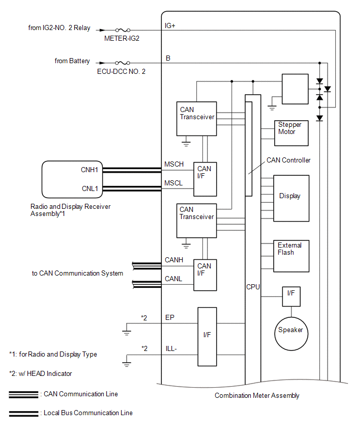
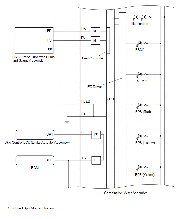
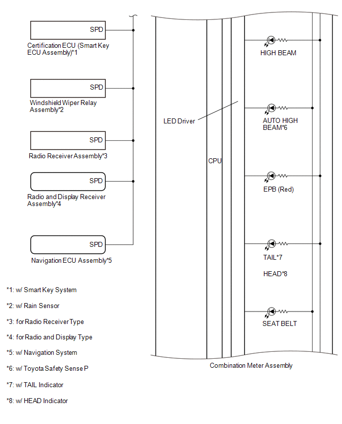
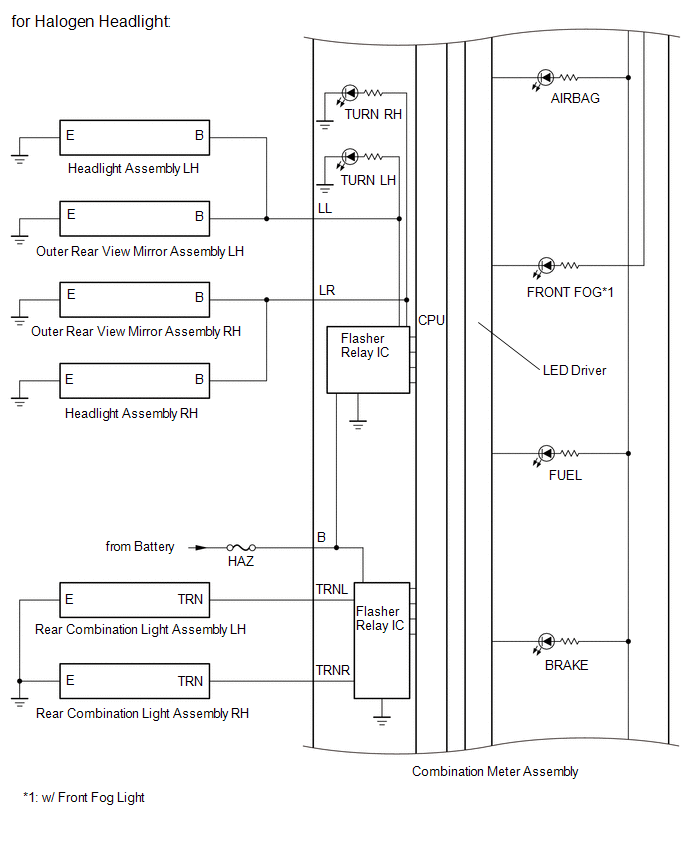
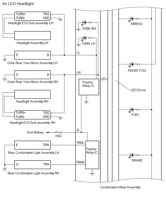
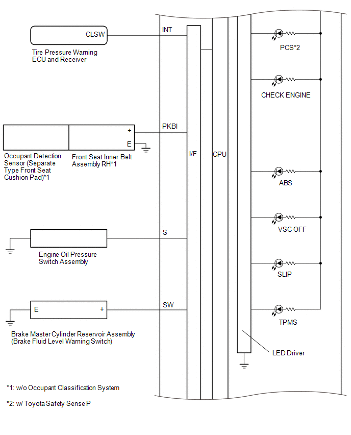
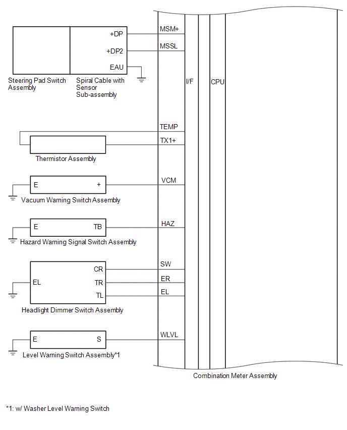
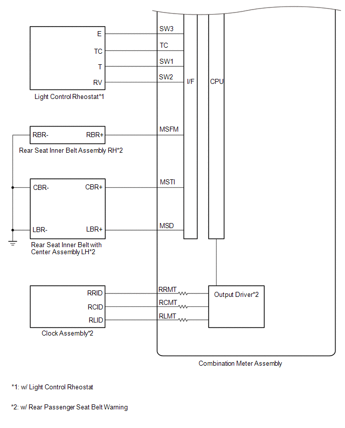
SYSTEM DIAGRAM
HINT:
Inspect the communication function by CAN communication system.
Click here .gif)
 Parts Location
PARTS LOCATION
ILLUSTRATION
*A
w/ Toyota Safety Sense P
*B
for LED Headlight
*1
THERMISTOR ASSEMBLY (AMBIENT TEMPERATURE SEN ...
 System Description
SYSTEM DESCRIPTION
INPUT AND OUTPUT SIGNALS OF COMBINATION METER ASSEMBLY
(a) Meter or Gauge
Item
Condition
Input/Output
Communication line
Si ...
Other materials:
Toyota CH-R Service Manual > Charging System: Problem Symptoms Table
PROBLEM SYMPTOMS TABLE
HINT:
Use the table below to help determine the cause of problem symptoms.
If multiple suspected areas are listed, the potential causes of the symptoms
are listed in order of probability in the "Suspected Area" column of the
table. Check each sy ...
Toyota CH-R Service Manual > Power Window Regulator Motor(for Rear Door): Inspection
INSPECTION
CAUTION / NOTICE / HINT
NOTICE:
Do not apply positive (+) battery voltage to any terminals, except terminal
2 (B), to avoid damaging the pulse sensor inside the motor.
Perform initialization of the power window system after removing, inspecting
or replacing the powe ...
Toyota C-HR (AX20) 2023-2026 Owner's Manual
Toyota CH-R Owners Manual
- For safety and security
- Instrument cluster
- Operation of each component
- Driving
- Interior features
- Maintenance and care
- When trouble arises
- Vehicle specifications
- For owners
Toyota CH-R Service Manual
- Introduction
- Maintenance
- Audio / Video
- Cellular Communication
- Navigation / Multi Info Display
- Park Assist / Monitoring
- Brake (front)
- Brake (rear)
- Brake Control / Dynamic Control Systems
- Brake System (other)
- Parking Brake
- Axle And Differential
- Drive Shaft / Propeller Shaft
- K114 Cvt
- 3zr-fae Battery / Charging
- Networking
- Power Distribution
- Power Assist Systems
- Steering Column
- Steering Gear / Linkage
- Alignment / Handling Diagnosis
- Front Suspension
- Rear Suspension
- Tire / Wheel
- Tire Pressure Monitoring
- Door / Hatch
- Exterior Panels / Trim
- Horn
- Lighting (ext)
- Mirror (ext)
- Window / Glass
- Wiper / Washer
- Door Lock
- Heating / Air Conditioning
- Interior Panels / Trim
- Lighting (int)
- Meter / Gauge / Display
- Mirror (int)
- Power Outlets (int)
- Pre-collision
- Seat
- Seat Belt
- Supplemental Restraint Systems
- Theft Deterrent / Keyless Entry

0.0101