Toyota CH-R Service Manual: Parts Location
PARTS LOCATION
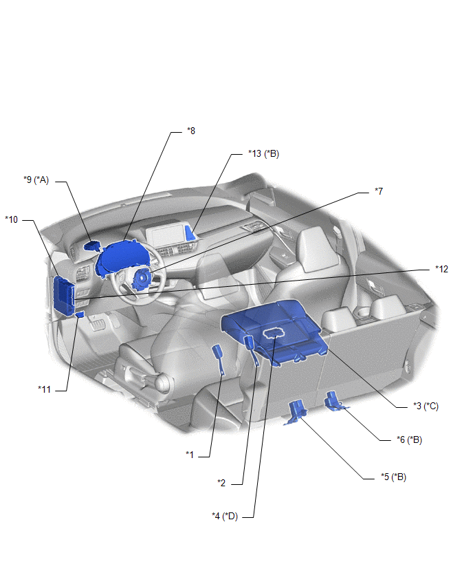
ILLUSTRATION
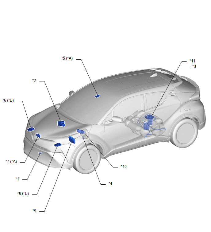
|
*A |
w/ Toyota Safety Sense P |
*B |
for LED Headlight |
|
*1 |
THERMISTOR ASSEMBLY (AMBIENT TEMPERATURE SENSOR) |
*2 |
SKID CONTROL ECU (BRAKE ACTUATOR ASSEMBLY) |
|
*3 |
FUEL SENDER GAUGE ASSEMBLY |
*4 |
VACUUM WARNING SWITCH ASSEMBLY |
|
*5 |
FORWARD RECOGNITION CAMERA |
*6 |
HEADLIGHT ECU SUB-ASSEMBLY RH |
|
*7 |
MILLIMETER WAVE RADAR SENSOR ASSEMBLY |
*8 |
HEADLIGHT ECU SUB-ASSEMBLY LH |
|
*9 |
ECM |
*10 |
BRAKE MASTER CYLINDER RESERVOIR ASSEMBLY (BRAKE FLUID LEVEL WARNING SWITCH) |
|
*11 |
FUEL SUCTION TUBE WITH PUMP AND GAUGE ASSEMBLY |
- |
- |
ILLUSTRATION
|
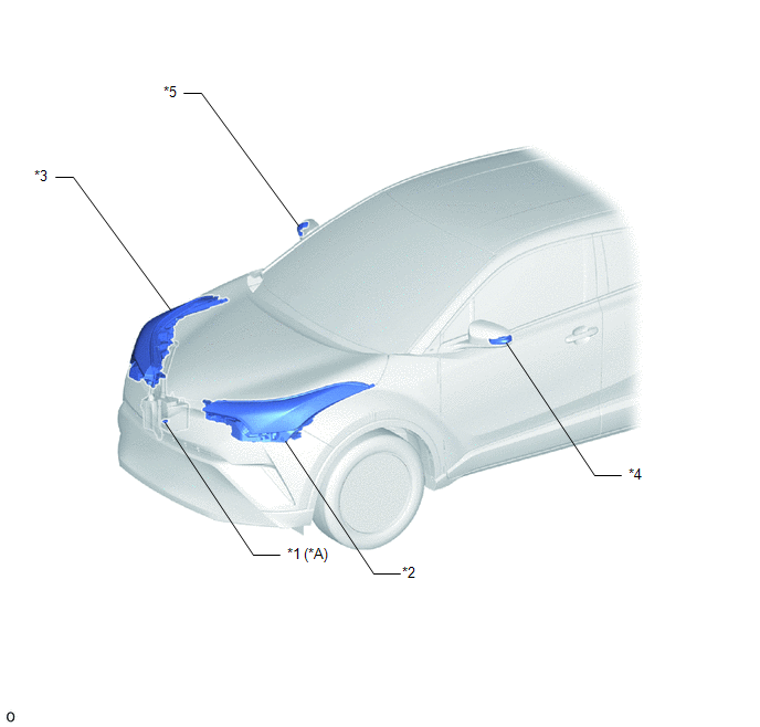
*A |
w/ Washer Level Warning Switch |
- |
- |
|
*1 |
LEVEL WARNING SWITCH ASSEMBLY |
*2 |
HEADLIGHT ASSEMBLY LH |
|
*3 |
HEADLIGHT ASSEMBLY RH |
*4 |
SIDE TURN SIGNAL LIGHT ASSEMBLY LH |
|
*5 |
SIDE TURN SIGNAL LIGHT ASSEMBLY RH |
- |
- |
ILLUSTRATION
|
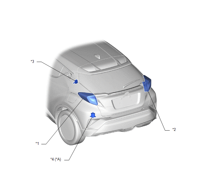
*A |
w/ Blind Spot Monitor System |
- |
- |
|
*1 |
REAR COMBINATION LIGHT ASSEMBLY LH |
*2 |
REAR COMBINATION LIGHT ASSEMBLY RH |
|
*3 |
TIRE PRESSURE WARNING ECU AND RECEIVER |
*4 |
BLIND SPOT MONITOR SENSOR LH |
ILLUSTRATION
|
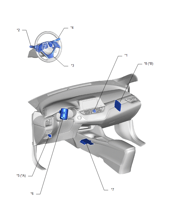
*A |
w/ Light Control Rheostat |
*B |
w/ Smart Key System |
|
*1 |
HAZARD WARNING SIGNAL SWITCH |
*2 |
HEADLIGHT DIMMER SWITCH ASSEMBLY |
|
*3 |
STEERING PAD SWITCH ASSEMBLY |
*4 |
WINDSHIELD WIPER SWITCH ASSEMBLY |
|
*5 |
LIGHT CONTROL RHEOSTAT |
*6 |
POWER STEERING ECU ASSEMBLY |
|
*7 |
AIRBAG SENSOR ASSEMBLY |
*8 |
CERTIFICATION ECU (SMART KEY ECU ASSEMBLY) |
ILLUSTRATION
|
*A |
w/ Rain Sensor |
*B |
w/ Rear Seat Belt Warning |
|
*C |
w/o Occupant Classification System |
*D |
w/ Occupant Classification System |
|
*1 |
FRONT SEAT INNER BELT ASSEMBLY (DRIVER SEAT) |
*2 |
FRONT SEAT INNER BELT ASSEMBLY (FRONT PASSENGER SEAT) |
|
*3 |
OCCUPANT DETECTION SENSOR (SEPARATE TYPE FRONT CUSHION PAD) |
*4 |
OCCUPANT DETECTION ECU |
|
*5 |
REAR SEAT INNER BELT WITH CENTER ASSEMBLY LH |
*6 |
REAR SEAT INNER BELT ASSEMBLY RH |
|
*7 |
SPIRAL CABLE WITH SENSOR SUB-ASSEMBLY |
*8 |
COMBINATION METER ASSEMBLY |
|
*9 |
WINDSHIELD WIPER RELAY ASSEMBLY |
*10 |
INSTRUMENT PANEL JUNCTION BLOCK ASSEMBLY - METER IG2 FUSE - ECU DDC NO.2 FUSE |
|
*11 |
DLC3 |
*12 |
MAIN BODY ECU (MULTIPLEX NETWORK BODY ECU) |
|
*13 |
CLOCK ASSEMBLY |
- |
- |
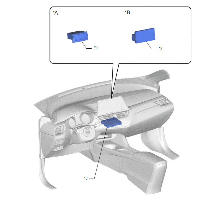
ILLUSTRATION
|
*A |
for Radio Receiver Type |
*B |
for Radio and Display Type |
|
*1 |
Radio Receiver Assembly |
*2 |
Radio and Display Receiver Assembly |
|
*3 |
Navigation Computer Assembly |
- |
- |
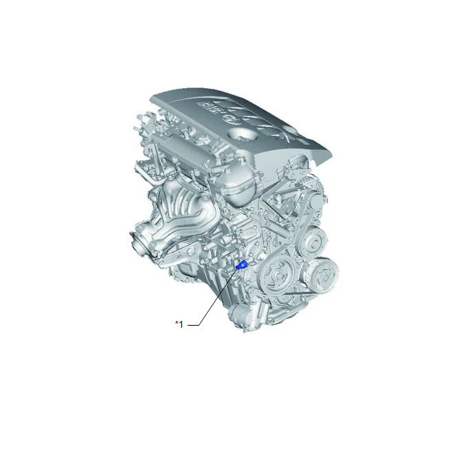
ILLUSTRATION
|
*1 |
ENGINE OIL PRESSURE SWITCH ASSEMBLY |
- |
- |
 Precaution
PRECAUTION
FUEL RECEIVER GAUGE OPERATION
(a) OPERATION
The combination meter assembly uses the fuel injection volume signal from the
ECM, fuel sender gauge assembly to detect the amount of fuel r ...
 System Diagram
SYSTEM DIAGRAM
HINT:
Inspect the communication function by CAN communication system.
Click here
...
Other materials:
Toyota CH-R Service Manual > Steering System: Problem Symptoms Table
PROBLEM SYMPTOMS TABLE
HINT:
Use the table below to help determine the cause of problem symptoms.
If multiple suspected areas are listed, the potential causes of the symptoms
are listed in order of probability in the "Suspected Area" column of the
table. Check each sy ...
Toyota CH-R Service Manual > Lin Communication System: Data List / Active Test
DATA LIST / ACTIVE TEST
DATA LIST
HINT:
Using the Techstream to read the Data List allows the values or states of switches,
sensors, actuators and other items to be read without removing any parts. This non-intrusive
inspection can be very useful because intermittent conditions or signals may ...
Toyota C-HR (AX20) 2023-2026 Owner's Manual
Toyota CH-R Owners Manual
- For safety and security
- Instrument cluster
- Operation of each component
- Driving
- Interior features
- Maintenance and care
- When trouble arises
- Vehicle specifications
- For owners
Toyota CH-R Service Manual
- Introduction
- Maintenance
- Audio / Video
- Cellular Communication
- Navigation / Multi Info Display
- Park Assist / Monitoring
- Brake (front)
- Brake (rear)
- Brake Control / Dynamic Control Systems
- Brake System (other)
- Parking Brake
- Axle And Differential
- Drive Shaft / Propeller Shaft
- K114 Cvt
- 3zr-fae Battery / Charging
- Networking
- Power Distribution
- Power Assist Systems
- Steering Column
- Steering Gear / Linkage
- Alignment / Handling Diagnosis
- Front Suspension
- Rear Suspension
- Tire / Wheel
- Tire Pressure Monitoring
- Door / Hatch
- Exterior Panels / Trim
- Horn
- Lighting (ext)
- Mirror (ext)
- Window / Glass
- Wiper / Washer
- Door Lock
- Heating / Air Conditioning
- Interior Panels / Trim
- Lighting (int)
- Meter / Gauge / Display
- Mirror (int)
- Power Outlets (int)
- Pre-collision
- Seat
- Seat Belt
- Supplemental Restraint Systems
- Theft Deterrent / Keyless Entry

0.0089