Toyota CH-R Service Manual: Diagnosis System
DIAGNOSIS SYSTEM
OBD II (w/ Canister Pump Module)
(a) When troubleshooting OBD II (On-Board Diagnostics) vehicles, an OBD II scan tool (complying with SAE J1978) must be connected to the DLC3 (Data Link Connector 3) of the vehicle. Various data in the vehicle ECM (Engine Control Module) can be then read.
(b) OBD II regulations require that the vehicle on-board computer illuminate the MIL (Malfunction Indicator Lamp) on the instrument panel when the computer detects a malfunction in:

(1) The emission control system components.
(2) The powertrain control components (which affect vehicle emissions).
(3) The computer itself.
In addition, the applicable DTCs prescribed by SAE J2012 are recorded in the ECM memory. If the malfunction does not recur in 3 consecutive trips, the MIL turns off automatically but the DTCs remain recorded in the ECM memory.
(c) To check for DTCs, connect the Techstream to the DLC3. The Techstream displays DTCs, freeze frame data, and a variety of engine data. The DTCs and freeze frame data can be cleared with the Techstream. In order to enhance OBD function on vehicles and develop the off-board diagnosis system, Controller Area Network (CAN) communication is used in this system. CAN is a network which uses a pair of data transmission lines spanning multiple computers and sensors. It allows for high speed communications between the systems and simplification of the wire harness connections.
Click here
.gif)
EURO-OBD (w/o Canister Pump Module)
(a) When troubleshooting Europe On-Board Diagnostic (Euro-OBD) vehicles, the vehicle must be connected to an OBD scan tool (complying with ISO 15765-4). Various data output from the vehicle ECM can then be read.
(b) Euro-OBD regulations require that the vehicle on-board computer illuminate the Malfunction Indicator Lamp (MIL) on the instrument panel when the computer detects a malfunction in any of the following:

(1) The emission control system/components
(2) The powertrain control components (which affect vehicle emissions)
(3) The computer
In addition, the applicable Diagnostic Trouble Codes (DTCs) prescribed by ISO 15765-4 are recorded in the ECM memory.
If the malfunction does not recur in 3 consecutive trips, the MIL goes off automatically but the DTCs remain recorded in the ECM memory.
(c) To check DTCs, connect the Techstream or OBD scan tool to the Data Link Connector 3 (DLC3) of the vehicle. The scan tool displays DTCs, freeze frame data and a variety of engine data.
The DTCs and freeze frame data can be cleared with the scan tool.
Click here
NORMAL MODE AND CHECK MODE
(a) Techstream only:
The diagnosis system operates in normal mode during normal vehicle use. In normal mode, 2 trip detection logic is used to ensure accurate detection of malfunctions. Check mode is also available as an option for technicians. In check mode, 1 trip detection logic is used for duplicating malfunction symptoms and increasing the system's ability to detect malfunctions, including intermittent problems.
2 TRIP DETECTION LOGIC
(a) When a malfunction is first detected, the malfunction is temporarily stored in the ECM memory (1st trip). If the same malfunction is detected during the subsequent driving cycle, the MIL is illuminated (2nd trip).
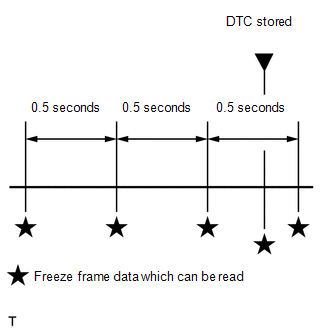
FREEZE FRAME DATA
(a) The ECM records vehicle and driving condition information as freeze frame data the moment a DTC is stored. When troubleshooting, freeze frame data can be helpful in determining whether the vehicle was moving or stationary, whether the engine was warmed up or not and whether the air-fuel ratio was lean or rich, as well as other data recorded at the time of a malfunction.
(b) The Techstream displays freeze frame data recorded at five different points: 1) 3 times before the DTC is stored, 2) once when the DTC is stored, and 3) once after the DTC is stored. The data can be used to reproduce the vehicle condition around the time of the malfunction. The data may be helpful in determining the cause of a malfunction. It may also be helpful in determining whether a DTC is being caused by a temporary malfunction.
LIST OF FREEZE FRAME DATA
Powertrain > Engine and ECT|
Tester Display |
|---|
|
Vehicle Speed |
|
Engine Speed |
|
Calculate Load |
|
MAF |
|
Coolant Temp |
|
Throttle Motor DUTY |
|
N Range Status |
|
Starter Signal |
|
Neutral Position SW Signal |
|
Stop Light Switch |
|
A/C Signal |
|
Closed Throttle Position SW |
|
TC and TE1 |
|
SPD (NT) |
|
Shift SW Status (P Range) |
|
Pattern Switch (PWR/M) |
|
Shift SW Status (R Range) |
|
Shift SW Status (N Range) |
|
Shift SW Status (N,P Range) Supported |
|
Shift SW Status (N,P Range) |
|
Sports Shift Up SW |
|
Sports Shift Down SW |
|
Sports Mode Selection SW |
|
Shift SW Status (D Range) |
|
A/T Oil Temperature 1 |
|
ATF Thermal Degradation Estimate |
|
NT Sensor Voltage |
|
SPD (NIN) |
|
SPD (NOUT) |
|
NOUT Sensor Voltage |
|
A/T Oil Pressure |
|
G Sensor |
|
Lock Up |
|
Shift Status |
|
Solenoid (SLS) |
|
SLU Solenoid Status |
|
SL Solenoid Status |
|
Solenoid(SC) |
|
Solenoid(SLP) |
|
G Sensor Calibration |
|
G Sensor Learning Value |
|
CVT Oil Press Calibration |
CHECK DATA LINK CONNECTOR 3 (DLC3)
(a) Check the DLC3.
Click here
CHECK BATTERY VOLTAGE
Standard voltage:
11 to 14 V
If voltage is below 11 V, replace or recharge the battery before proceeding to the next step.
MIL (Malfunction Indicator Lamp)
(a) Check that the MIL illuminates when the ignition switch is turned to ON.
If the MIL does not illuminate, there is a problem in the MIL circuit.
- w/ Canister Pump Module:
Click here
- w/o Canister Pump Module:
Click here
(b) When the engine is started, the MIL goes off.
 Terminals Of Ecm
TERMINALS OF ECM
ECM
HINT:
The standard voltage and resistance of each ECM terminal is shown in the table
below.
In the table, first follow the information under "Condition". Look un ...
 Dtc Check / Clear
DTC CHECK / CLEAR
NOTICE:
When the diagnosis system is changed from normal mode to check mode or vice versa,
all DTCs and freeze frame data recorded in normal mode are cleared. Before changing
m ...
Other materials:
Toyota CH-R Service Manual > Vehicle Stability Control System: Speed Sensor Rotor Faulty (C1237)
DESCRIPTION
The skid control ECU (brake actuator assembly) measures the speed of each wheel
by receiving signals from each speed sensor.
These signals are used for recognizing that all four wheels are operating properly.
Therefore, signals from all wheels must be equal.
DTC No.
...
Toyota CH-R Service Manual > Safety Connect System: Unable To Connect To Call Center
DESCRIPTION
This may occur when the intensity of telephone radio frequency was very weak,
or the safety connect system has a malfunction and a DTC is set.
PROCEDURE
1.
CHECK COMMUNICATION SERVICE CONDITION
(a) Move the vehicle.
(1) If the vehicle is outside the ...
Toyota C-HR (AX20) 2023-2026 Owner's Manual
Toyota CH-R Owners Manual
- For safety and security
- Instrument cluster
- Operation of each component
- Driving
- Interior features
- Maintenance and care
- When trouble arises
- Vehicle specifications
- For owners
Toyota CH-R Service Manual
- Introduction
- Maintenance
- Audio / Video
- Cellular Communication
- Navigation / Multi Info Display
- Park Assist / Monitoring
- Brake (front)
- Brake (rear)
- Brake Control / Dynamic Control Systems
- Brake System (other)
- Parking Brake
- Axle And Differential
- Drive Shaft / Propeller Shaft
- K114 Cvt
- 3zr-fae Battery / Charging
- Networking
- Power Distribution
- Power Assist Systems
- Steering Column
- Steering Gear / Linkage
- Alignment / Handling Diagnosis
- Front Suspension
- Rear Suspension
- Tire / Wheel
- Tire Pressure Monitoring
- Door / Hatch
- Exterior Panels / Trim
- Horn
- Lighting (ext)
- Mirror (ext)
- Window / Glass
- Wiper / Washer
- Door Lock
- Heating / Air Conditioning
- Interior Panels / Trim
- Lighting (int)
- Meter / Gauge / Display
- Mirror (int)
- Power Outlets (int)
- Pre-collision
- Seat
- Seat Belt
- Supplemental Restraint Systems
- Theft Deterrent / Keyless Entry

0.0071