Toyota CH-R Service Manual: Installation
INSTALLATION
PROCEDURE
1. INSTALL NO. 3 ANTENNA CORD SUB-ASSEMBLY
(a) w/o Manual (SOS) Switch
|
(1) Engage the clamp and guide to temporarily install the No. 3 antenna cord sub-assembly. |
|
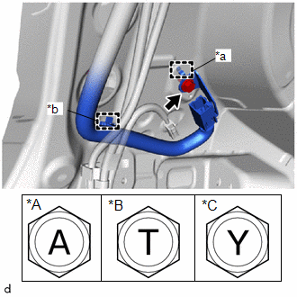
(2) Install the bolt.
Torque:
for Type A :
10.5 N·m {107 kgf·cm, 8 ft·lbf}
for Type B :
10 N·m {102 kgf·cm, 7 ft·lbf}
for Type C :
10 N·m {102 kgf·cm, 7 ft·lbf}
(b) w/ Manual (SOS) Switch
|
(1) Engage the clamp and guide to temporarily install the No. 3 antenna cord sub-assembly. |
|
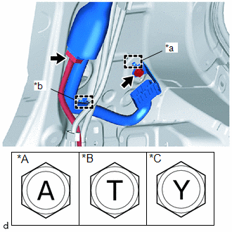
(2) Install the bolt.
(3) Connect the connector of the floor wire.
Torque:
for Type A :
10.5 N·m {107 kgf·cm, 8 ft·lbf}
for Type B :
10 N·m {102 kgf·cm, 7 ft·lbf}
for Type C :
10 N·m {102 kgf·cm, 7 ft·lbf}
|
(c) Engage the clamps install the No. 3 antenna cord sub-assembly. |
|
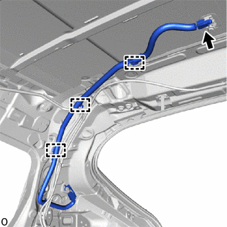
(d) Connect the connector.
2. INSTALL NO. 2 ANTENNA CORD SUB-ASSEMBLY
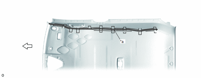
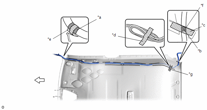
(a) Type A:
(1) Remove the old double-sided tape from the roof headlining.
|
*a |
Marking |
- |
- |
 |
Double-sided Tape |
.png) |
Front |
(2) Prepare an appropriate amount of new double-sided tape.
HINT:
Be careful not to touch the adhesive surface.
(3) Apply the double-sided tape to the roof headlining while aligning the tape with the markings on the roof headlining.
(4) Peel off the release paper from the double-sided tape.
|
*a |
Marking Tape (A) |
*b |
Marking Tape (B) |
|
*c |
Adhesive Tape (A) |
*d |
Adhesive Tape (B) |
|
*e |
Protrusion |
*f |
Edge of the roof headlining |
|
*g |
Adjustment Area |
- |
- |
|
|
Front |
- |
- |
(5) Align the marking tape (A) on the No. 2 antenna cord sub-assembly with the protrusion on the front of the roof headlining and wrap tape around the No. 2 antenna cord sub-assembly and protrusion of the roof headlining.
(6) Install the No. 2 antenna cord sub-assembly on the double-sided tape of the roof headlining.
NOTICE:
- Make sure that there are no gaps between the roof headlining and No. 2 antenna cord sub-assembly, and that the No. 2 antenna cord sub-assembly is not twisted.
- Make sure the No. 2 antenna cord assembly is securely installed. If any part of the No. 2 antenna cord sub-assembly is loose, it will cause an abnormal noise.
(7) Align the marking tape (B) on the No. 2 antenna cord sub-assembly with the edge of roof headlining on the roof headlining and secure the No. 2 antenna cord sub-assembly with the adhesive tape (A) as shown in the illustration.
NOTICE:
Make sure that there are no gaps between the roof headlining and No. 2 antenna cord sub-assembly, and that the No. 2 antenna cord sub-assembly is not twisted.
(8) Apply the 2 adhesive tapes (B) as shown in the illustration to secure the No. 2 antenna cord subassembly.
HINT:
Secure the extra length of the No. 2 antenna cord sub-assembly in the adjustment area as shown in the illustration.
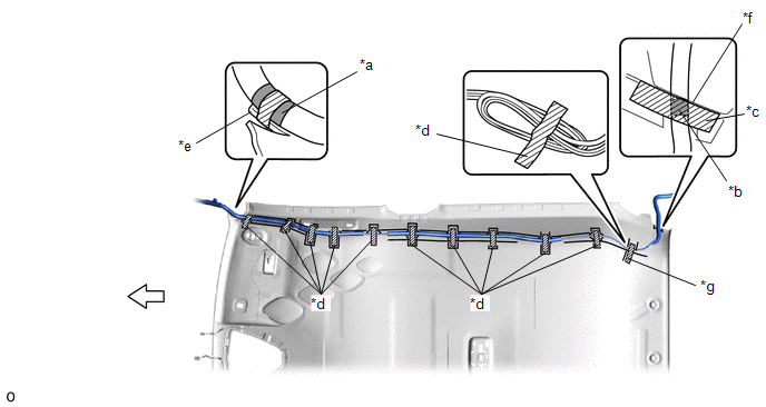
(b) Type B:
(1) Align the marking tape (A) on the No. 2 antenna cord sub-assembly with the protrusion on the front of the roof headlining and wrap tape around the No. 2 antenna cord sub-assembly and protrusion of the roof headlining.
|
*a |
Marking Tape (A) |
*b |
Marking Tape (B) |
|
*c |
Adhesive Tape (A) |
*d |
Adhesive Tape (B) |
|
*e |
Protrusion |
*f |
Edge of the roof headlining |
|
*g |
Adjustment Area |
- |
- |
|
|
Front |
- |
- |
(2) Install the No. 2 antenna cord sub-assembly on the butyl tape of the roof headlining.
NOTICE:
- Make sure that there are no gaps between the roof headlining and No. 2 antenna cord sub-assembly, and that the No. 2 antenna cord sub-assembly is not twisted.
- Make sure the No. 2 antenna cord assembly is securely installed. If any part of the No. 2 antenna cord sub-assembly is loose, it will cause an abnormal noise.
(3) Align the marking tape (B) on the No. 2 antenna cord sub-assembly with the edge of roof headlining on the roof headlining and secure the No. 2 antenna cord sub-assembly with the adhesive tape (A) as shown in the illustration.
NOTICE:
Make sure that there are no gaps between the roof headlining and No. 2 antenna cord sub-assembly, and that the No. 2 antenna cord sub-assembly is not twisted.
(4) Apply the 11 adhesive tapes (B) as shown in the illustration to secure the No. 2 antenna cord subassembly.
HINT:
Secure the extra length of the No. 2 antenna cord sub-assembly in the adjustment area as shown in the illustration.
3. INSTALL ROOF HEADLINING
Click here
.gif)
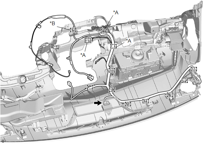
4. INSTALL ANTENNA CORD SUB-ASSEMBLY
(a) Engage the clamps to install the antenna cord sub-assembly.
|
*A |
w/ USB Audio System |
*B |
w/ Manual (SOS) Switch |
(b) w/ Manual (SOS) Switch:
(1) Connect the connector.
5. INSTALL NO. 3 HEATER TO REGISTER DUCT SUB-ASSEMBLY
Click here
6. INSTALL INSTRUMENT PANEL SAFETY PAD
Click here
 Components
COMPONENTS
ILLUSTRATION
*1
ANTENNA CORD SUB-ASSEMBLY
*2
NO. 3 HEATER TO REGISTER DUCT SUB-ASSEMBLY
ILLUSTRATION
*A
Ty ...
 Removal
REMOVAL
CAUTION / NOTICE / HINT
The necessary procedures (adjustment, calibration, initialization, or registration)
that must be performed after parts are removed and installed, or replaced the du ...
Other materials:
Toyota CH-R Service Manual > Tire Pressure Warning System: Tire Pressure Monitor Receiver Communication Stop (B1247)
DESCRIPTION
The main body ECU (multiplex network body ECU) and tire pressure warning ECU
and receiver are connected using 2 direct lines that they use to communicate with
each other.
DTC No.
Detection Item
DTC Detection Condition
Trouble Area
...
Toyota CH-R Service Manual > Rear Door Speaker: Installation
INSTALLATION
CAUTION / NOTICE / HINT
HINT:
Use the same procedure for the RH and LH sides.
The procedure listed below is for the LH side.
PROCEDURE
1. INSTALL REAR SPEAKER ASSEMBLY
(a) Engage the claw and guide to temporarily install the rear speaker
assembly.
...
Toyota C-HR (AX20) 2023-2026 Owner's Manual
Toyota CH-R Owners Manual
- For safety and security
- Instrument cluster
- Operation of each component
- Driving
- Interior features
- Maintenance and care
- When trouble arises
- Vehicle specifications
- For owners
Toyota CH-R Service Manual
- Introduction
- Maintenance
- Audio / Video
- Cellular Communication
- Navigation / Multi Info Display
- Park Assist / Monitoring
- Brake (front)
- Brake (rear)
- Brake Control / Dynamic Control Systems
- Brake System (other)
- Parking Brake
- Axle And Differential
- Drive Shaft / Propeller Shaft
- K114 Cvt
- 3zr-fae Battery / Charging
- Networking
- Power Distribution
- Power Assist Systems
- Steering Column
- Steering Gear / Linkage
- Alignment / Handling Diagnosis
- Front Suspension
- Rear Suspension
- Tire / Wheel
- Tire Pressure Monitoring
- Door / Hatch
- Exterior Panels / Trim
- Horn
- Lighting (ext)
- Mirror (ext)
- Window / Glass
- Wiper / Washer
- Door Lock
- Heating / Air Conditioning
- Interior Panels / Trim
- Lighting (int)
- Meter / Gauge / Display
- Mirror (int)
- Power Outlets (int)
- Pre-collision
- Seat
- Seat Belt
- Supplemental Restraint Systems
- Theft Deterrent / Keyless Entry

0.0083