Toyota CH-R Service Manual: Components
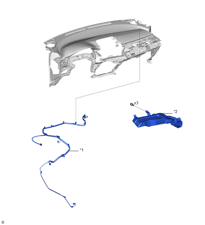
COMPONENTS
ILLUSTRATION
|
*1 |
ANTENNA CORD SUB-ASSEMBLY |
*2 |
NO. 3 HEATER TO REGISTER DUCT SUB-ASSEMBLY |
ILLUSTRATION
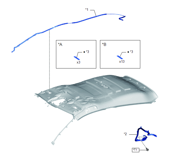
|
*A |
Type A |
*B |
Type B |
|
*1 |
NO. 2 ANTENNA CORD SUB-ASSEMBLY |
*2 |
NO. 3 ANTENNA CORD SUB-ASSEMBLY |
|
*3 |
ADHESIVE TAPE |
- |
- |
.png) |
N*m (kgf*cm, ft.*lbf): Specified torque |
● |
Non-reusable part |
|
*T1 |
for Type A: 10.5 N*m (107 kgf*cm, 8 ft.*lbf) for Type B: 10 N*m (102 kgf*cm, 7 ft.*lbf) for Type C: 10 N*m (102 kgf*cm, 7 ft.*lbf) |
- |
- |

 Installation
INSTALLATION
PROCEDURE
1. INSTALL NO. 3 ANTENNA CORD SUB-ASSEMBLY
(a) w/o Manual (SOS) Switch
(1) Engage the clamp and guide to temporarily install the No. 3 antenna
cord sub-assemb ...
Other materials:
Toyota CH-R Service Manual > Meter / Gauge / Display: Clock
Components
COMPONENTS
ILLUSTRATION
*A
w/o Display
-
-
*1
CLOCK ASSEMBLY
*2
INSTRUMENT CLUSTER FINISH CENTER PANEL SUB-ASSEMBLY
ILLUSTRATION
*A
w/ Display
...
Toyota CH-R Owners Manual > Driving procedures: Engine (ignition) switch (vehicles without a smart key system)
Starting the engine
Check that the parking brake is set.
Check that the shift lever is in P.
Firmly depress the brake pedal.
Turn the engine switch to the "START" position to start the engine.
Changing the engine switch positions
"LOCK"
The steering wheel is lo ...
Toyota C-HR (AX20) 2023-2026 Owner's Manual
Toyota CH-R Owners Manual
- For safety and security
- Instrument cluster
- Operation of each component
- Driving
- Interior features
- Maintenance and care
- When trouble arises
- Vehicle specifications
- For owners
Toyota CH-R Service Manual
- Introduction
- Maintenance
- Audio / Video
- Cellular Communication
- Navigation / Multi Info Display
- Park Assist / Monitoring
- Brake (front)
- Brake (rear)
- Brake Control / Dynamic Control Systems
- Brake System (other)
- Parking Brake
- Axle And Differential
- Drive Shaft / Propeller Shaft
- K114 Cvt
- 3zr-fae Battery / Charging
- Networking
- Power Distribution
- Power Assist Systems
- Steering Column
- Steering Gear / Linkage
- Alignment / Handling Diagnosis
- Front Suspension
- Rear Suspension
- Tire / Wheel
- Tire Pressure Monitoring
- Door / Hatch
- Exterior Panels / Trim
- Horn
- Lighting (ext)
- Mirror (ext)
- Window / Glass
- Wiper / Washer
- Door Lock
- Heating / Air Conditioning
- Interior Panels / Trim
- Lighting (int)
- Meter / Gauge / Display
- Mirror (int)
- Power Outlets (int)
- Pre-collision
- Seat
- Seat Belt
- Supplemental Restraint Systems
- Theft Deterrent / Keyless Entry

0.0067