Toyota CH-R Service Manual: Security Indicator Light Does not Blink
DESCRIPTION
The transponder key ECU assembly blinks the security indicator light when the immobiliser is set.
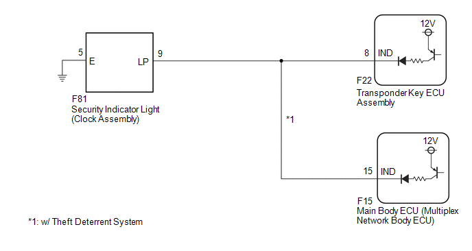
WIRING DIAGRAM
CAUTION / NOTICE / HINT
NOTICE:
If the transponder key ECU assembly is replaced, refer to Registration.
Click here .gif)
PROCEDURE
|
1. |
SYSTEM CHECK |
(a) Check the vehicle specification.
|
Result |
Proceed to |
|---|---|
|
w/o Theft Deterrent System |
A |
|
w/ Theft Deterrent System |
B |
| B | .gif) |
GO TO STEP 5 |
|
.gif)
|
2. |
PERFORM ACTIVE TEST USING TECHSTREAM (SECURITY INDICATOR) |
(a) Connect the Techstream to the DLC3.
(b) Turn the ignition switch to ON.
(c) Turn the Techstream on.
(d) Enter the following menus: Body Electrical / Immobiliser / Active Test.
(e) Perform the Active Test according to the display on the Techstream.
Body Electrical > Immobiliser > Active Test|
Tester Display |
Measurement Item |
Control Range |
Diagnostic Note |
|---|---|---|---|
|
Security Indicator |
Security indicator light |
ON/OFF |
- |
|
Tester Display |
|---|
|
Security Indicator |
OK:
Security indicator light can be turned on and off using the Techstream.
| OK | |
REPLACE TRANSPONDER KEY ECU ASSEMBLY |
|
|
3. |
CHECK HARNESS AND CONNECTOR (TRANSPONDER KEY ECU ASSEMBLY - SECURITY INDICATOR LIGHT AND BODY GROUND) |
(a) Disconnect F22 transponder key ECU assembly connector.
(b) Disconnect the F81 security indicator light connector.
(c) Measure the resistance according to the value(s) in the table below.
Standard Resistance:
|
Tester Connection |
Condition |
Specified Condition |
|---|---|---|
|
F81-9 (LP) - F22-8 (IND) |
Always |
Below 1 Ω |
|
F81-9 (LP) - Body ground |
Always |
10 kΩ or higher |
|
F22-8 (IND) - Body ground |
Always |
10 kΩ or higher |
|
F81-5 (E) - Body ground |
Always |
Below 1 Ω |
| NG | |
REPAIR OR REPLACE HARNESS OR CONNECTOR |
|
|
4. |
CHECK TRANSPONDER KEY ECU ASSEMBLY (TERMINAL IND) |
(a) Connect the F22 transponder key ECU assembly connector.
(b) Measure the voltage according to the value(s) in the table below.
Standard Voltage:
|
Tester Connection |
Condition |
Specified Condition |
|---|---|---|
|
F81-9 (LP) - Body ground |
Key not in ignition key cylinder |
Pulse generation |
|
Key in ignition key cylinder |
Below 1 V |
| OK | |
REPLACE SECURITY INDICATOR LIGHT (CLOCK ASSEMBLY)
|
| NG | |
REPLACE TRANSPONDER KEY ECU ASSEMBLY |
|
5. |
PERFORM ACTIVE TEST USING TECHSTREAM (SECURITY INDICATOR) |
(a) Connect the Techstream to the DLC3.
(b) Turn the ignition switch to ON.
(c) Turn the Techstream on.
(d) Enter the following menus: Body Electrical / Immobiliser or Main Body / Active Test.
(e) Perform the Active Test according to the display on the Techstream.
Body Electrical > Immobiliser > Active Test|
Tester Display |
Measurement Item |
Control Range |
Diagnostic Note |
|---|---|---|---|
|
Security Indicator |
Security indicator light |
ON/OFF |
- |
|
Tester Display |
|---|
|
Security Indicator |
|
Tester Display |
Measurement Item |
Control Range |
Diagnostic Note |
|---|---|---|---|
|
Security Indicator |
Security indicator light |
ON/OFF |
- |
|
Tester Display |
|---|
|
Security Indicator |
|
Result |
Proceed to |
|---|---|
|
Security indicator light operation is normal when performing the "Main Body" and "Immobiliser" Active Test |
A |
|
B |
|
C |
|
Security indicator light operation is not normal when performing the "Main Body" and "Immobiliser" Active Test |
D |
| B | |
GO TO STEP 7 |
| C | |
GO TO STEP 8 |
| D | |
GO TO STEP 9 |
|
|
6. |
CHECK SECURITY INDICATOR LIGHT OPERATION |
(a) When the immobiliser is set, check that the security indicator light blinks.*1
OK:
The security indicator light blinks normally.
(b) When the theft deterrent system is in the arming preparation state, check that the security indicator light is on.*2
Click here
OK:
The security indicator light is on.
|
Result |
Proceed to |
|---|---|
|
Both *1 and *2 are OK |
A |
|
*1 is NG (*2 is OK) |
B |
|
*2 is NG (*1 is OK) |
C |
|
Both *1 and *2 are NG |
D |
| A | |
USE SIMULATION METHOD TO CHECK |
| B | |
REPLACE TRANSPONDER KEY ECU ASSEMBLY |
| C | |
REPLACE MAIN BODY ECU (MULTIPLEX NETWORK BODY ECU) |
| D | |
REPLACE SECURITY INDICATOR LIGHT (CLOCK ASSEMBLY)
|
|
7. |
CHECK HARNESS AND CONNECTOR (SECURITY INDICATOR LIGHT - TRANSPONDER KEY ECU ASSEMBLY) |
(a) Disconnect the F81 security indicator light connector.
(b) Disconnect the F22 transponder key ECU assembly connector.
(c) Measure the resistance according to the value(s) in the table below.
Standard Resistance:
|
Tester Connection |
Condition |
Specified Condition |
|---|---|---|
|
F22-8 (IND) - F81-9 (LP) |
Always |
Below 1 Ω |
|
F22-8 (IND) - Body ground |
Always |
10 kΩ or higher |
|
F81-9 (LP) - Body ground |
Always |
10 kΩ or higher |
| OK | |
REPLACE TRANSPONDER KEY ECU ASSEMBLY |
| NG | |
REPAIR OR REPLACE HARNESS OR CONNECTOR |
|
8. |
CHECK HARNESS AND CONNECTOR (SECURITY INDICATOR LIGHT - MAIN BODY ECU) |
(a) Disconnect the F81 security indicator light connector.
(b) Disconnect the F15 main body ECU (multiplex network body ECU) connector.
(c) Measure the resistance according to the value(s) in the table below.
Standard Resistance:
|
Tester Connection |
Condition |
Specified Condition |
|---|---|---|
|
F15-15 (IND) - F81-9 (LP) |
Always |
Below 1 Ω |
|
F15-15 (IND) - Body ground |
Always |
10 kΩ or higher |
|
F81-9 (LP) - Body ground |
Always |
10 kΩ or higher |
| OK | |
REPLACE MAIN BODY ECU (MULTIPLEX NETWORK BODY ECU) |
| NG | |
REPAIR OR REPLACE HARNESS OR CONNECTOR |
|
9. |
CHECK HARNESS AND CONNECTOR (SECURITY INDICATOR LIGHT - MAIN BODY ECU OR TRANSPONDER KEY ECU) |
(a) Disconnect the F81 security indicator light connector.
(b) Disconnect F22 transponder key ECU assembly connector.
(c) Disconnect the F15 main body ECU (multiplex network body ECU) connector.
(d) Measure the resistance according to the value(s) in the table below.
Standard Resistance:
|
Tester Connection |
Condition |
Specified Condition |
|---|---|---|
|
F22-8 (IND) - F81-9 (LP) |
Always |
Below 1 Ω |
|
F15-15 (IND) - F81-9 (LP) |
Always |
Below 1 Ω |
|
F22-8 (IND) - Body ground |
Always |
10 kΩ or higher |
|
F15-15 (IND) - Body ground |
Always |
10 kΩ or higher |
|
F81-9 (LP) - Body ground |
Always |
10 kΩ or higher |
|
F81-5 (E) - Body ground |
Always |
Below 1 Ω |
| NG | |
REPAIR OR REPLACE HARNESS OR CONNECTOR |
|
|
10. |
REPLACE SECURITY INDICATOR LIGHT |
(a) Temporarily replace the security indicator light (clock assembly) with a new or known good one.
Click here
(b) When the immobiliser is set or theft deterrent system is in the arming preparation state, check that the security indicator light blinks.
OK:
Security indicator light blinks.
| OK | |
END (SECURITY INDICATOR LIGHT WAS DEFECTIVE) |
|
|
11. |
REPLACE TRANSPONDER KEY ECU ASSEMBLY |
(a) Replace the transponder key ECU assembly with a new or known good one.
Click here
HINT:
Refer to Registration.
Click here
(b) When the immobiliser is set or theft deterrent system is in the arming preparation state, check that the security indicator light blinks.
OK:
Security indicator light blinks.
| OK | |
END (TRANSPONDER KEY ECU ASSEMBLY WAS DEFECTIVE) |
| NG | |
REPLACE MAIN BODY ECU (MULTIPLEX NETWORK BODY ECU) |
 Key Cannot be Registered
DESCRIPTION
A maximum of 5 master key ID codes and 3 sub key ID codes can be registered.
WIRING DIAGRAM
Click here
CAUTION / NOTICE / HINT
NOTICE:
If the transponder key ECU assembly is replac ...
 Relay
Relay
Inspection
INSPECTION
PROCEDURE
1. INSPECT SECURITY WARNING RELAY
(a) Check the resistance.
(1) Measure the resistance according to the value(s) in the table below.
Standard Res ...
Other materials:
Toyota CH-R Service Manual > Power Mirror Control System: Precaution
PRECAUTION
IGNITION SWITCH EXPRESSIONS
(a) The type of ignition switch used on this model differs depending on the specifications
of the vehicle. The expressions listed in the table below are used in this section.
Expression
Ignition Switch (Position)
Engine Swi ...
Toyota CH-R Service Manual > Rear View Monitor System: Diagnostic Trouble Code Chart
DIAGNOSTIC TROUBLE CODE CHART
Rear View Monitor System
DTC No.
Detection Item
Link
C1622
Back Camera Disconnected
...
Toyota C-HR (AX20) 2023-2026 Owner's Manual
Toyota CH-R Owners Manual
- For safety and security
- Instrument cluster
- Operation of each component
- Driving
- Interior features
- Maintenance and care
- When trouble arises
- Vehicle specifications
- For owners
Toyota CH-R Service Manual
- Introduction
- Maintenance
- Audio / Video
- Cellular Communication
- Navigation / Multi Info Display
- Park Assist / Monitoring
- Brake (front)
- Brake (rear)
- Brake Control / Dynamic Control Systems
- Brake System (other)
- Parking Brake
- Axle And Differential
- Drive Shaft / Propeller Shaft
- K114 Cvt
- 3zr-fae Battery / Charging
- Networking
- Power Distribution
- Power Assist Systems
- Steering Column
- Steering Gear / Linkage
- Alignment / Handling Diagnosis
- Front Suspension
- Rear Suspension
- Tire / Wheel
- Tire Pressure Monitoring
- Door / Hatch
- Exterior Panels / Trim
- Horn
- Lighting (ext)
- Mirror (ext)
- Window / Glass
- Wiper / Washer
- Door Lock
- Heating / Air Conditioning
- Interior Panels / Trim
- Lighting (int)
- Meter / Gauge / Display
- Mirror (int)
- Power Outlets (int)
- Pre-collision
- Seat
- Seat Belt
- Supplemental Restraint Systems
- Theft Deterrent / Keyless Entry

0.0069