Toyota CH-R Service Manual: Key Cannot be Registered
DESCRIPTION
A maximum of 5 master key ID codes and 3 sub key ID codes can be registered.
WIRING DIAGRAM
Click here .gif)
CAUTION / NOTICE / HINT
NOTICE:
If the transponder key ECU assembly is replaced, refer to Registration.
Click here
PROCEDURE
|
1. |
CHECK REGISTRATION MODE |
(a) Check that the system enters registration mode.
OK:
System enters registration mode.
| NG | .gif) |
GO TO STEP 5 |
|
.gif)
|
2. |
CHECK SECURITY INDICATOR LIGHT OPERATION |
(a) In registration mode, insert the key into the ignition key cylinder and check the security indicator light.
HINT:
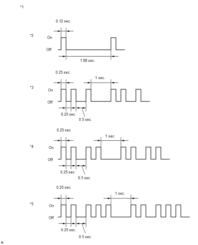
If the new key ID code registration fails, code 2-1 will be output through the security light. Trying to re-register an already registered key will cause code 2-2 to be output when the key is inserted. If the number of registered key ID codes exceeds the maximum limit, code 2-3 will be output through the security indicator light. The output details are shown in the following illustration.
|
*1 |
Security Indicator Light |
*2 |
Normal (Immobiliser system is operating normally) |
|
*3 |
Code 2-1 |
*4 |
Code 2-2 |
|
*5 |
Code 2-3 |
- |
- |
|
Result |
Proceed to |
|---|---|
|
Code 2-1 or Code 2-3 is output |
A |
|
Code 2-2 is output |
B |
| B | |
END (REGISTERED KEY WAS USED) |
|
|
3. |
READ VALUE USING TECHSTREAM (TRANSPONDER S-CODE, TRANSPONDER M-CODE) |
(a) Connect the Techstream to the DLC3.
(b) Turn the ignition switch to ON.
(c) Turn the Techstream on.
(d) Enter the following menus: Body Electrical / Immobiliser / Data List.
(e) Read the Data List according to the display on the Techstream.
Body Electrical > Immobiliser > Data List|
Tester Display |
Measurement Item |
Range |
Normal Condition |
Diagnostic Note |
|---|---|---|---|---|
|
Transponder S-code |
Number of registered sub key |
min. 0, max. 15 |
Number of registered sub key |
- |
|
Transponder M-code |
Number of registered master key |
min. 0, max. 15 |
Number of registered master key |
- |
|
Tester Display |
|---|
|
Transponder S-code |
|
Transponder M-code |
|
Result |
Proceed to |
|---|---|
|
5 is displayed for "Transponder M-code" and 0 is displayed for "Transponder S-code" |
A |
|
0 is displayed for "Transponder M-code" and 3 is displayed for "Transponder S-code" |
B |
|
5 is displayed for "Transponder M-code" and 3 is displayed for "Transponder S-code" |
C |
|
Values are other than above |
D |
| A | |
KEY REGISTRATION (SUB-KEY) |
| B | |
KEY REGISTRATION (MASTER KEY) |
| C | |
MAXIMUM NUMBER OF KEYS ALREADY REGISTERED |
|
|
4. |
KEY REGISTRATION |
(a) Refer to the table below to determine if additional keys can be registered.
|
Number of Keys Registered (Master and Sub) |
Proceed to |
|---|---|
|
0 |
New key ID code registration |
|
1 to 7 |
Additional key ID code registration |
(b) Check if an additional key can be registered.
OK:
Additional key can be registered.
| OK | |
END (KEY MALFUNCTION) |
| NG | |
REPLACE TRANSPONDER KEY ECU ASSEMBLY |
|
5. |
INSPECT UNLOCK WARNING SWITCH ASSEMBLY |
(a) Remove the unlock warning switch assembly.
Click here
(b) Inspect the unlock warning switch assembly.
Click here
| NG | |
REPLACE UNLOCK WARNING SWITCH ASSEMBLY |
|
|
6. |
CHECK HARNESS AND CONNECTOR (TRANSPONDER KEY ECU ASSEMBLY - UNLOCK WARNING SWITCH ASSEMBLY) |
(a) Disconnect the F13 unlock warning switch assembly connector.
(b) Disconnect the F22 transponder key ECU assembly connector.
(c) Measure the resistance according to the value(s) in the table below.
Standard Resistance:
|
Tester Connection |
Condition |
Specified Condition |
|---|---|---|
|
F13-1 (UN+) - F22-3 (KSW) |
Always |
Below 1 Ω |
|
F13-2 (UN-) - Body ground |
Always |
Below 1 Ω |
|
F13-1 (UN+) - Body ground |
Always |
10 kΩ or higher |
|
F22-3 (KSW) - Body ground |
Always |
10 kΩ or higher |
| OK | |
REPLACE TRANSPONDER KEY ECU ASSEMBLY |
| NG | |
REPAIR OR REPLACE HARNESS OR CONNECTOR |
 Engine does not Start but Initial Combustion Occurs
DESCRIPTION
If the key ID codes of the key and transponder key ECU assembly match, the immobiliser
system is unset and the engine start permission signal is sent to the ECM. When
the ID codes of ...
 Security Indicator Light Does not Blink
DESCRIPTION
The transponder key ECU assembly blinks the security indicator light when the
immobiliser is set.
WIRING DIAGRAM
CAUTION / NOTICE / HINT
NOTICE:
If the transponder key ECU assembl ...
Other materials:
Toyota CH-R Service Manual > Blower Unit(for Denso Made): Installation
INSTALLATION
PROCEDURE
1. INSTALL BLOWER ASSEMBLY
(a) Engage the guides to install the air conditioning radiator assembly.
(b) Install the 2 screws.
(c) Engage the guides.
(d) ...
Toyota CH-R Service Manual > Seat Belt Warning System(w/o Occupant Classification System): Terminals Of Ecu
TERMINALS OF ECU
CHECK MAIN BODY ECU (MULTIPLEX NETWORK BODY ECU) AND INSTRUMENT PANEL JUNCTION
BLOCK ASSEMBLY
*A
Main Body ECU (Multiplex Network Body ECU) with 1 Connector
-
-
*A
Main Body ECU (Multiplex Network Bo ...
Toyota C-HR (AX20) 2023-2026 Owner's Manual
Toyota CH-R Owners Manual
- For safety and security
- Instrument cluster
- Operation of each component
- Driving
- Interior features
- Maintenance and care
- When trouble arises
- Vehicle specifications
- For owners
Toyota CH-R Service Manual
- Introduction
- Maintenance
- Audio / Video
- Cellular Communication
- Navigation / Multi Info Display
- Park Assist / Monitoring
- Brake (front)
- Brake (rear)
- Brake Control / Dynamic Control Systems
- Brake System (other)
- Parking Brake
- Axle And Differential
- Drive Shaft / Propeller Shaft
- K114 Cvt
- 3zr-fae Battery / Charging
- Networking
- Power Distribution
- Power Assist Systems
- Steering Column
- Steering Gear / Linkage
- Alignment / Handling Diagnosis
- Front Suspension
- Rear Suspension
- Tire / Wheel
- Tire Pressure Monitoring
- Door / Hatch
- Exterior Panels / Trim
- Horn
- Lighting (ext)
- Mirror (ext)
- Window / Glass
- Wiper / Washer
- Door Lock
- Heating / Air Conditioning
- Interior Panels / Trim
- Lighting (int)
- Meter / Gauge / Display
- Mirror (int)
- Power Outlets (int)
- Pre-collision
- Seat
- Seat Belt
- Supplemental Restraint Systems
- Theft Deterrent / Keyless Entry

0.0199