Toyota CH-R Service Manual: Engine does not Start but Initial Combustion Occurs
DESCRIPTION
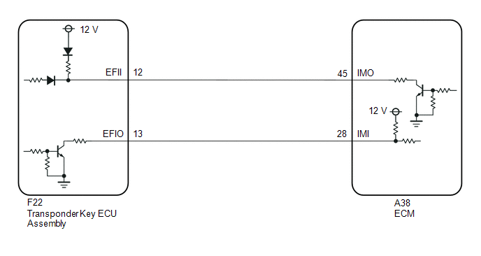
If the key ID codes of the key and transponder key ECU assembly match, the immobiliser system is unset and the engine start permission signal is sent to the ECM. When the ID codes of the transponder key ECU assembly and ECM match, the engine starts.
WIRING DIAGRAM
CAUTION / NOTICE / HINT
NOTICE:
If the transponder key ECU assembly or ECM is replaced, refer to Registration.
Click here .gif)
PROCEDURE
|
1. |
CLEAR DTC |
(a) Clear the DTCs.
Powertrain > Engine and ECT > Clear DTCs
|
.gif)
|
2. |
CHECK FOR DTC |
(a) Check for DTCs.
Body Electrical > Immobiliser > Trouble Codes Powertrain > Engine and ECT > Trouble CodesOK:
DTC is not output.
|
Result |
Proceed to |
|---|---|
|
DTCs are not output |
A |
|
DTCs are output |
B |
| B | .gif) |
GO TO DIAGNOSTIC TROUBLE CODE CHART |
|
|
3. |
READ VALUE USING TECHSTREAM (IMMOBILISER FUEL CUT) |
(a) Connect the Techstream to the DLC3.
(b) Turn the ignition switch to ON.
(c) Turn the Techstream on.
(d) Enter the following menus: Body Electrical / Engine / Active Test.
(e) Perform the Active Test according to the display on the Techstream.
Powertrain > Engine and ECT > Data List|
Tester Display |
Measurement Item |
Range |
Normal Condition |
Diagnostic Note |
|---|---|---|---|---|
|
Immobiliser Fuel Cut |
Status of immobiliser system fuel cut |
OFF/ON |
- |
- |
|
Tester Display |
|---|
|
Immobiliser Fuel Cut |
OK:
OFF is displayed after the engine is started.
| Result |
Proceed to |
|---|---|
| OK (w/o Canister Pump Module) |
A |
| OK (w/ Canister Pump Module) |
B |
| NG |
C |
| A | |
GO TO SFI SYSTEM |
| B | |
GO TO SFI SYSTEM |
|
|
4. |
CHECK WHETHER ENGINE STARTS |
(a) Using a registered key, turn the ignition switch to ON.
(b) Check that the engine starts 5 seconds after the ignition switch was turned to ON.
OK:
Engine starts normally.
|
Result |
Proceed to |
|---|---|
|
Engine can be started |
A |
|
Engine cannot be started |
B |
| A | |
USE SIMULATION METHOD TO CHECK |
|
|
5. |
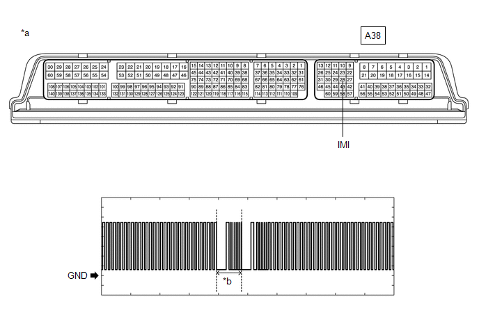
CHECK ECM (TERMINAL IMI) |
(a) Using an oscilloscope, check the waveform
|
*a |
Component with harness connected (ECM) |
*b |
Waveform |
|
Item |
Content |
|---|---|
|
Tester Connection |
A38-28 (IMI) - Body ground |
|
Tool Setting |
2 V/DIV., 500 ms./DIV. |
|
Condition |
Ignition switch ON |
|
Result |
Proceed to |
|---|---|
|
Normal waveform |
A |
|
Waveform not output, or has abnormal wavelength or shape |
B |
| B | |
GO TO STEP 11 |
|
|
6. |
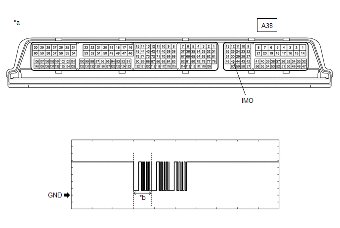
CHECK ECM (TERMINAL IMO) |
(a) Using an oscilloscope, check the waveform
|
*a |
Component with harness connected (ECM) |
*b |
Waveform |
|
Item |
Content |
|---|---|
|
Tester Connection |
A38-45 (IMO) - Body ground |
|
Tool Setting |
2 V/DIV., 500 ms./DIV. |
|
Condition |
Within 3 seconds of the ignition switch first being turned to ON after cable is disconnected and reconnected to the negative (-) battery terminal |
|
Result |
Proceed to |
|---|---|
|
Normal waveform |
A |
|
Waveform not output, or has abnormal wavelength or shape |
B |
| B | |
REPLACE ECM |
|
|
7. |
REGISTER ECU COMMUNICATION ID |
(a) Register the communication ID between the transponder key ECU assembly and ECM.
HINT:
Refer to Registration.
Click here
|
|
8. |
CHECK WHETHER ENGINE STARTS |
(a) Using a registered key, turn the ignition switch to ON.
(b) Check that the engine starts 5 seconds after the ignition switch was turned to ON.
OK:
Engine starts normally.
|
Result |
Proceed to |
|---|---|
|
Engine can be started |
A |
|
Engine cannot be started |
B |
| A | |
END (REGISTERED COMMUNICATION ID WAS DEFECTIVE) |
|
|
9. |
REPLACE TRANSPONDER KEY ECU ASSEMBLY |
(a) Replace the transponder key ECU assembly with a new one.
Click here
HINT:
Refer to Registration.
Click here
NOTICE:
Key ID code registration is necessary when replacing the transponder key ECU assembly.
Click here
|
|
10. |
CHECK WHETHER ENGINE STARTS |
(a) Using a registered key, turn the ignition switch to ON.
(b) Check that the engine starts 5 seconds after the ignition switch was turned to ON.
OK:
Engine starts normally.
| Result |
Proceed to |
|---|---|
| OK |
A |
| NG (w/o Canister Pump Module) |
B |
| NG (w/ Canister Pump Module) |
C |
| A | |
END (TRANSPONDER KEY ECU ASSEMBLY WAS DEFECTIVE) |
| B | |
GO TO SFI SYSTEM |
| C | |
GO TO SFI SYSTEM |
|
11. |
CHECK HARNESS AND CONNECTOR (TRANSPONDER KEY ECU ASSEMBLY - ECM) |
(a) Disconnect the F22 transponder key ECU assembly connector
(b) Disconnect the A38 ECM connector
(c) Measure the resistance according to the value(s) in the table below
Standard Resistance:
|
Tester Connection |
Condition |
Specified Condition |
|---|---|---|
|
F22-13 (EFIO) - A38-28 (IMI) |
Always |
Below 1 Ω |
|
F22-13 (EFIO) - Body ground |
Always |
10 kΩ or higher |
|
A38-28 (IMI) - Body ground |
Always |
10 kΩ or higher |
| OK | |
REPLACE TRANSPONDER KEY ECU ASSEMBLY |
| NG | |
REPAIR OR REPLACE HARNESS OR CONNECTOR |
 Engine does not Start because No Initial Combustion
DESCRIPTION
When a key is inserted into the ignition key cylinder, the transponder
key coil receives the key ID code and sends it to the transponder key ECU
assembly.
If an error i ...
 Key Cannot be Registered
DESCRIPTION
A maximum of 5 master key ID codes and 3 sub key ID codes can be registered.
WIRING DIAGRAM
Click here
CAUTION / NOTICE / HINT
NOTICE:
If the transponder key ECU assembly is replac ...
Other materials:
Toyota CH-R Service Manual > Navigation System: Voice Recognition Microphone Disconnected (B1579)
DESCRIPTION
The radio and display receiver assembly and map light assembly (telephone microphone
assembly) are connected to each other using the microphone connection detection
signal lines.
This DTC is stored when a microphone connection detection signal line is disconnected.
DTC ...
Toyota CH-R Service Manual > Electric Parking Brake System: Dtc Check / Clear
DTC CHECK / CLEAR
CHECK DTC AND FREEZE FRAME DATA (USING TECHSTREAM)
(a) Turn the ignition switch off.
(b) Connect the Techstream to the DLC3.
(c) Turn the ignition switch to ON.
(d) Turn the Techstream on.
(e) Enter the following menus: Chassis / ABS/VSC/TRAC/EPB / Trouble Codes.
Chassis > ...
Toyota C-HR (AX20) 2023-2026 Owner's Manual
Toyota CH-R Owners Manual
- For safety and security
- Instrument cluster
- Operation of each component
- Driving
- Interior features
- Maintenance and care
- When trouble arises
- Vehicle specifications
- For owners
Toyota CH-R Service Manual
- Introduction
- Maintenance
- Audio / Video
- Cellular Communication
- Navigation / Multi Info Display
- Park Assist / Monitoring
- Brake (front)
- Brake (rear)
- Brake Control / Dynamic Control Systems
- Brake System (other)
- Parking Brake
- Axle And Differential
- Drive Shaft / Propeller Shaft
- K114 Cvt
- 3zr-fae Battery / Charging
- Networking
- Power Distribution
- Power Assist Systems
- Steering Column
- Steering Gear / Linkage
- Alignment / Handling Diagnosis
- Front Suspension
- Rear Suspension
- Tire / Wheel
- Tire Pressure Monitoring
- Door / Hatch
- Exterior Panels / Trim
- Horn
- Lighting (ext)
- Mirror (ext)
- Window / Glass
- Wiper / Washer
- Door Lock
- Heating / Air Conditioning
- Interior Panels / Trim
- Lighting (int)
- Meter / Gauge / Display
- Mirror (int)
- Power Outlets (int)
- Pre-collision
- Seat
- Seat Belt
- Supplemental Restraint Systems
- Theft Deterrent / Keyless Entry

0.0402