Toyota CH-R Service Manual: Adjustment
ADJUSTMENT
CAUTION / NOTICE / HINT
The necessary procedures (adjustment, calibration, initialization, or registration) that must be performed after completing the rear wheel alignment procedure are shown below.
Necessary Procedures After Procedure Performed|
Replaced Part or Performed Procedure |
Necessary Procedure |
Effect/Inoperative Function when Necessary Procedure not Performed |
Link |
|---|---|---|---|
|
Rear wheel alignment adjustment |
|
|
|
PROCEDURE
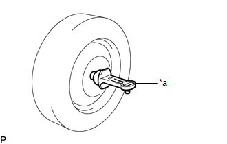
1. INSPECT TIRES
Click here
.gif)
2. MEASURE VEHICLE HEIGHT
Click here
3. INSPECT CAMBER
NOTICE:
Inspect while the vehicle is unloaded.
|
(a) Install a camber-caster-kingpin gauge. |
|
(b) Inspect the camber.
Camber (Unloaded Vehicle):
|
Vehicle Model |
Camber Inclination |
Right-left Difference |
|---|---|---|
|
ZGX10L-AHXEPX ZGX10L-AHXGPX ZGX10L-AHXNPX |
-0°43' +/- 0°45' (-0.72° +/- 0.75°) |
0°45' (0.75°) or less |
|
ZGX10L-BHXNPA |
-0°51' +/- 0°45' (-0.85° +/- 0.75°) |
0°45' (0.75°) or less |
HINT:
Camber is not adjustable. If the measurement is not within the specified range, inspect the suspension parts for damage and/or wear, and replace them if necessary.
4. INSPECT TOE-IN
NOTICE:
Inspect while the vehicle is unloaded.
(a) Bounce the vehicle up and down at the corners to stabilize the suspension.
(b) Release the parking brake and move the shift lever to N.
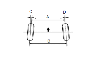
(c) Push the vehicle straight ahead approximately 5 m (16.4 ft.). (Step A)
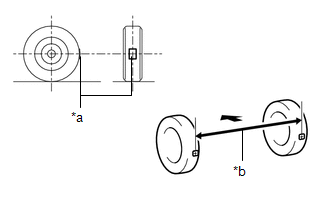
(d) Put tread center marks on the rearmost points of the rear wheels and measure the distance between the marks (dimension B).
|
*a |
Tread Center Mark |
|
*b |
Dimension B |
.png) |
Front of the Vehicle |
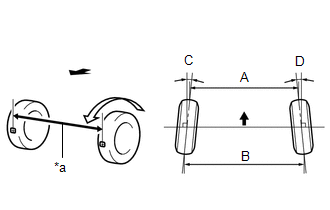
(e) Slowly push the vehicle straight ahead to cause the rear wheels to rotate 180°. Use the rear tire valve as a reference point.
HINT:
Do not allow the wheels to rotate more than 180°. If the wheels rotate more than 180°, perform the procedure from step A again.
(f) Measure the distance between the tread center marks on the front of the rear wheels (dimension A).
|
*a |
Dimension A |
|
|
Front of the Vehicle |
Toe-in (Unloaded Vehicle):
|
Vehicle Model |
Specified Condition |
|---|---|
|
ZGX10L-AHXEPX ZGX10L-AHXGPX ZGX10L-AHXNPX |
C + D: 0°10' +/- 0°10' (0.17° +/- 0.17°) |
|
B - A: 2.0 +/- 2.0 mm (0.0787 +/- 0.0787 in.) |
|
|
ZGX10L-BHXNPA |
C + D: 0°17' +/- 0°10' (0.28° +/- 0.17°) |
|
B - A: 3.0 +/- 2.0 mm (0.118 +/- 0.0787 in.) |
HINT:
Measure "B - A" only when "C + D" cannot be measured.
If the toe-in is not within the specified range, adjust it at the rear suspension toe adjust cam sub-assembly.
5. ADJUST TOE-IN
|
(a) Loosen the nut of the rear No. 2 suspension arm assembly (on the rear suspension member sub-assembly side). NOTICE: Hold the rear suspension toe adjust cam sub-assembly while rotating the nut. |
|
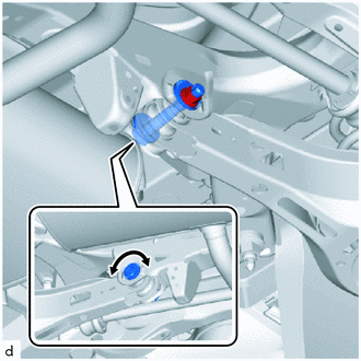
(b) Rotate the rear suspension toe adjust cam sub-assembly to adjust the toe-in.
Toe-in (Unloaded Vehicle):
|
Vehicle Model |
Specified Condition |
|---|---|
|
ZGX10L-AHXEPX ZGX10L-AHXGPX ZGX10L-AHXNPX |
C + D: 0°10' +/- 0°05' (0.17° +/- 0.08°) |
|
B - A: 2.0 +/- 1.0 mm (0.0787 +/- 0.0394 in.) |
|
|
ZGX10L-BHXNPA |
C + D: 0°17' +/- 0°05' (0.28° +/- 0.08°) |
|
B - A: 3.0 +/- 1.0 mm (0.118 +/- 0.0394 in.) |
HINT:
- Rotating the rear suspension toe adjust cam sub-assembly by one notch changes the toe by approximately 2.9 mm (0.114 in.).
- Perform adjustments so that the value is as close as possible to the median of the specified range.
|
|
Front of the Vehicle |
(c) Tighten the nut of the rear No. 2 suspension arm assembly (on the rear suspension member sub-assembly side).
Torque:
100 N·m {1020 kgf·cm, 74 ft·lbf}
NOTICE:
Hold the rear suspension toe adjust cam sub-assembly while rotating the nut.
6. ALIGN FRONT WHEELS FACING STRAIGHT AHEAD
7. PERFORM YAW RATE AND ACCELERATION SENSOR CALIBRATION
Click here

 Front Suspension
...
Other materials:
Toyota CH-R Service Manual > Pre-collision System: Terminals Of Ecu
TERMINALS OF ECU
CHECK MILLIMETER WAVE RADAR SENSOR
(a) Measure the voltage and resistance according to the value(s) in the table
below.
HINT:
If the result is not as specified, there may be a malfunction on the wire harness
side.
Terminal No. (Symbol)
Wiring Color
...
Toyota CH-R Service Manual > Rear Seat Assembly: Installation
INSTALLATION
CAUTION / NOTICE / HINT
CAUTION:
Wear protective gloves. Sharp areas on the parts may injure your hands.
PROCEDURE
1. INSTALL REAR SEAT CUSHION LOCK HOOK
(a) Engage the claws to install a new rear seat cushion lock hook as shown in
the illustration.
HINT:
Use the same procedur ...
Toyota C-HR (AX20) 2023-2026 Owner's Manual
Toyota CH-R Owners Manual
- For safety and security
- Instrument cluster
- Operation of each component
- Driving
- Interior features
- Maintenance and care
- When trouble arises
- Vehicle specifications
- For owners
Toyota CH-R Service Manual
- Introduction
- Maintenance
- Audio / Video
- Cellular Communication
- Navigation / Multi Info Display
- Park Assist / Monitoring
- Brake (front)
- Brake (rear)
- Brake Control / Dynamic Control Systems
- Brake System (other)
- Parking Brake
- Axle And Differential
- Drive Shaft / Propeller Shaft
- K114 Cvt
- 3zr-fae Battery / Charging
- Networking
- Power Distribution
- Power Assist Systems
- Steering Column
- Steering Gear / Linkage
- Alignment / Handling Diagnosis
- Front Suspension
- Rear Suspension
- Tire / Wheel
- Tire Pressure Monitoring
- Door / Hatch
- Exterior Panels / Trim
- Horn
- Lighting (ext)
- Mirror (ext)
- Window / Glass
- Wiper / Washer
- Door Lock
- Heating / Air Conditioning
- Interior Panels / Trim
- Lighting (int)
- Meter / Gauge / Display
- Mirror (int)
- Power Outlets (int)
- Pre-collision
- Seat
- Seat Belt
- Supplemental Restraint Systems
- Theft Deterrent / Keyless Entry

0.0069