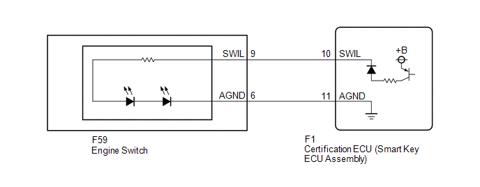
Toyota CH-R Service Manual: Engine Switch Illumination Circuit
DESCRIPTION
The illuminated entry system controls the engine switch illumination.
WIRING DIAGRAM
CAUTION / NOTICE / HINT
NOTICE:
Before replacing the certification ECU (smart key ECU assembly), refer to Registration.
Click here .gif)
PROCEDURE
|
1. |
PERFORM ACTIVE TEST USING TECHSTREAM |
(a) Connect the Techstream to the DLC3.
(b) Turn the engine switch on (IG).
(c) Turn the Techstream on.
(d) Enter the following menus: Body Electrical / Smart Key / Active Test.
(e) Perform the Active Test according to the display on the Techstream.
Body Electrical > Smart Key > Active Test|
Tester Display |
Measurement Item |
Control Range |
Diagnostic Note |
|---|---|---|---|
|
Power/Engine SW Light |
Engine switch illumination |
OFF or ON |
When performing this Active Test, make sure the following condition is met: The engine switch illumination is off (15 seconds or more have elapsed since it turned from on to off) and the engine switch is on (ACC) or on (IG), or the engine is running. |
|
Tester Display |
|---|
|
Power/Engine SW Light |
OK:
Engine switch illumination comes on.
| OK | .gif) |
PROCEED TO NEXT SUSPECTED AREA SHOWN IN PROBLEM SYMPTOMS TABLE
|
|
.gif)
|
2. |
INSPECT ENGINE SWITCH |
(a) Remove the engine switch.
Click here
(b) Inspect the engine switch.
Click here
OK:
Engine switch illumination is normal.
| NG | |
REPLACE ENGINE SWITCH |
|
|
3. |
CHECK HARNESS AND CONNECTOR (ENGINE SWITCH - CERTIFICATION ECU (SMART KEY ECU ASSEMBLY)) |
(a) Disconnect the F1 certification ECU (smart key ECU assembly) connector.
(b) Measure the resistance according to the value(s) in the table below.
Standard Resistance:
|
Tester Connection |
Condition |
Specified Condition |
|---|---|---|
|
F59-9 (SWIL) - F1-10 (SWIL) |
Always |
Below 1 Ω |
|
F59-6 (AGND) - F1-11 (AGND) |
Always |
Below 1 Ω |
|
F59-9 (SWIL) or F1-10 (SWIL) - Body ground |
Always |
10 kΩ or higher |
|
F59-6 (AGND) or F1-11 (AGND) - Body ground |
Always |
10 kΩ or higher |
| OK | |
REPLACE CERTIFICATION ECU (SMART KEY ECU ASSEMBLY) |
| NG | |
REPAIR OR REPLACE HARNESS OR CONNECTOR |
 Ambient Illumination Light Circuit
DESCRIPTION
The main body ECU (multiplex network body ECU) controls the ambient illumination
lights.
WIRING DIAGRAM
CAUTION / NOTICE / HINT
NOTICE:
Inspect the lights for circuits rel ...
 Door Unlock Detection Switch Circuit
DESCRIPTION
The main body ECU (multiplex network body ECU) detects the condition of each
door unlock detection switch.
WIRING DIAGRAM
CAUTION / NOTICE / HINT
NOTICE:
Before replacing the main ...
Other materials:
Toyota CH-R Service Manual > Audio And Visual System(for Radio Receiver Type): Portable Player cannot be Registered
CAUTION / NOTICE / HINT
HINT:
Some versions of "Bluetooth" compatible audio players may not function properly,
or the functions may be limited using the radio receiver assembly, even if the portable
audio player itself can play files.
Click here
PROCEDURE
1.
...
Toyota CH-R Service Manual > Brake Booster: Reassembly
REASSEMBLY
PROCEDURE
1. INSTALL VACUUM WARNING SWITCH ASSEMBLY
(a) Install a new check valve grommet to the brake booster assembly.
(b) Install the vacuum sensor assembly to the brake booster assembly
as shown in the illustration.
...
Toyota C-HR (AX20) 2023-2026 Owner's Manual
Toyota CH-R Owners Manual
- For safety and security
- Instrument cluster
- Operation of each component
- Driving
- Interior features
- Maintenance and care
- When trouble arises
- Vehicle specifications
- For owners
Toyota CH-R Service Manual
- Introduction
- Maintenance
- Audio / Video
- Cellular Communication
- Navigation / Multi Info Display
- Park Assist / Monitoring
- Brake (front)
- Brake (rear)
- Brake Control / Dynamic Control Systems
- Brake System (other)
- Parking Brake
- Axle And Differential
- Drive Shaft / Propeller Shaft
- K114 Cvt
- 3zr-fae Battery / Charging
- Networking
- Power Distribution
- Power Assist Systems
- Steering Column
- Steering Gear / Linkage
- Alignment / Handling Diagnosis
- Front Suspension
- Rear Suspension
- Tire / Wheel
- Tire Pressure Monitoring
- Door / Hatch
- Exterior Panels / Trim
- Horn
- Lighting (ext)
- Mirror (ext)
- Window / Glass
- Wiper / Washer
- Door Lock
- Heating / Air Conditioning
- Interior Panels / Trim
- Lighting (int)
- Meter / Gauge / Display
- Mirror (int)
- Power Outlets (int)
- Pre-collision
- Seat
- Seat Belt
- Supplemental Restraint Systems
- Theft Deterrent / Keyless Entry

0.009