Toyota CH-R Service Manual: Door Unlock Detection Switch Circuit
DESCRIPTION
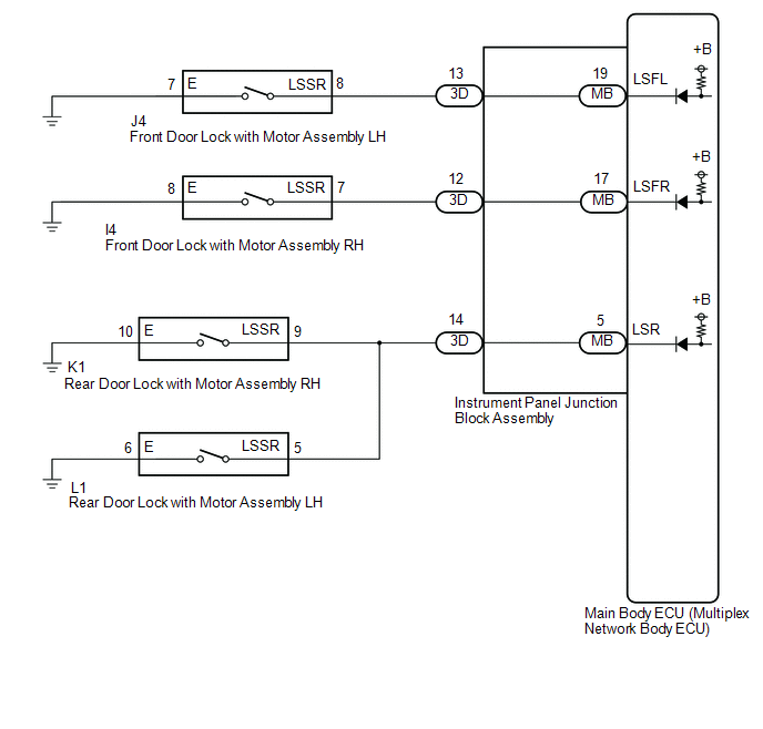
The main body ECU (multiplex network body ECU) detects the condition of each door unlock detection switch.
WIRING DIAGRAM
CAUTION / NOTICE / HINT
NOTICE:
Before replacing the main body ECU (multiplex network body ECU), refer to Registration*1.
Click here .gif)
- *1: w/ Smart Key System
PROCEDURE
|
1. |
READ VALUE USING TECHSTREAM |
(a) Connect the Techstream to the DLC3.
(b) Turn the ignition switch to ON.
(c) Turn the Techstream on.
(d) Enter the following menus: Body Electrical / Main Body / Data List.
(e) Read the Data List according to the display on the Techstream.
Body Electrical > Main Body > Data List|
Tester Display |
Measurement Item |
Range |
Normal Condition |
Diagnostic Note |
|---|---|---|---|---|
|
FR Door Lock Pos |
Front door RH unlock detection switch signal |
LOCK or UNLOCK |
LOCK: Front door RH locked UNLOCK: Front door RH unlocked |
- |
|
FL Door Lock Pos |
Front door LH unlock detection switch signal |
LOCK or UNLOCK |
LOCK: Front door LH locked UNLOCK: Front door LH unlocked |
- |
|
RR-Door Lock Pos SW |
Rear door RH and LH unlock detection switch signal |
ON or OFF |
ON: Rear door RH or LH unlocked OFF: Rear door RH and LH locked |
- |
|
RL-Door Lock Pos SW |
Rear door RH and LH unlock detection switch signal |
ON or OFF |
ON: Rear door RH or LH unlocked OFF: Rear door RH and LH locked |
- |
|
Tester Display |
|---|
|
FR Door Lock Pos |
|
FL Door Lock Pos |
|
RR-Door Lock Pos SW |
|
RL-Door Lock Pos SW |
|
Result |
Proceed to |
|---|---|
|
OK |
A |
|
"FL Door Lock Pos" is not normal |
B |
|
"FR Door Lock Pos" is not normal |
C |
|
Both "RL-Door Lock Pos SW" and "RR-Door Lock Pos SW" are not normal |
D |
| A | .gif) |
PROCEED TO NEXT SUSPECTED AREA SHOWN IN PROBLEM SYMPTOMS TABLE
|
| C | |
GO TO STEP 5 |
| D | |
GO TO STEP 8 |
|
.gif)
|
2. |
INSPECT FRONT DOOR LOCK WITH MOTOR ASSEMBLY LH |
(a) Remove the front door lock with motor assembly LH.
Click here
(b) Inspect the front door lock with motor assembly LH.
Click here
OK:
Front door lock with motor assembly LH is normal.
| NG | |
REPLACE FRONT DOOR LOCK WITH MOTOR ASSEMBLY LH
|
|
|
3. |
CHECK HARNESS AND CONNECTOR (FRONT DOOR LOCK ASSEMBLY LH - INSTRUMENT PANEL JUNCTION BLOCK ASSEMBLY AND BODY GROUND) |
(a) Disconnect the 3D instrument panel junction block assembly connector.
(b) Measure the resistance according to the value(s) in the table below.
Standard Resistance:
|
Tester Connection |
Condition |
Specified Condition |
|---|---|---|
|
J4-8 (LSSR) - 3D-13 |
Always |
Below 1 Ω |
|
J4-8 (LSSR) or 3D-13 - Body ground |
Always |
10 kΩ or higher |
|
J4-7 (E) - Body ground |
Always |
Below 1 Ω |
| NG | |
REPAIR OR REPLACE HARNESS OR CONNECTOR |
|
|
4. |
INSPECT INSTRUMENT PANEL JUNCTION BLOCK ASSEMBLY |
(a) Remove the instrument panel junction block assembly.
Click here
(b) Remove the main body ECU (multiplex network body ECU) from the instrument panel junction block assembly.
Click here
(c) Measure the resistance according to the value(s) in the table below.
|
*a |
Component without harness connected (Instrument Panel Junction Block Assembly) |
- |
- |
Standard Resistance:
|
Tester Connection |
Condition |
Specified Condition |
|---|---|---|
|
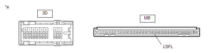
3D-13 - MB-19 (LSFL) |
Always |
Below 1 Ω |
| OK | |
REPLACE MAIN BODY ECU (MULTIPLEX NETWORK BODY ECU)
|
| NG | |
REPLACE INSTRUMENT PANEL JUNCTION BLOCK ASSEMBLY
|
|
5. |
INSPECT FRONT DOOR LOCK WITH MOTOR ASSEMBLY RH |
(a) Remove the front door lock with motor assembly RH.
Click here
(b) Inspect the front door lock with motor assembly RH.
Click here
OK:
Front door lock with motor assembly RH is normal.
| NG | |
REPLACE FRONT DOOR LOCK WITH MOTOR ASSEMBLY RH
|
|
|
6. |
CHECK HARNESS AND CONNECTOR (FRONT DOOR LOCK ASSEMBLY RH - INSTRUMENT PANEL JUNCTION BLOCK ASSEMBLY AND BODY GROUND) |
(a) Disconnect the 3D instrument panel junction block assembly connector.
(b) Measure the resistance according to the value(s) in the table below.
Standard Resistance:
|
Tester Connection |
Condition |
Specified Condition |
|---|---|---|
|
I4-7 (LSSR) - 3D-12 |
Always |
Below 1 Ω |
|
I4-7 (LSSR) or 3D-12 - Body ground |
Always |
10 kΩ or higher |
|
I4-8 (E) - Body ground |
Always |
Below 1 Ω |
| NG | |
REPAIR OR REPLACE HARNESS OR CONNECTOR |
|
|
7. |
INSPECT INSTRUMENT PANEL JUNCTION BLOCK ASSEMBLY |
(a) Remove the instrument panel junction block assembly.
Click here
(b) Remove the main body ECU (multiplex network body ECU) from the instrument panel junction block assembly.
Click here
(c) Measure the resistance according to the value(s) in the table below.
|
*a |
Component without harness connected (Instrument Panel Junction Block Assembly) |
- |
- |
Standard Resistance:
|
Tester Connection |
Condition |
Specified Condition |
|---|---|---|
|
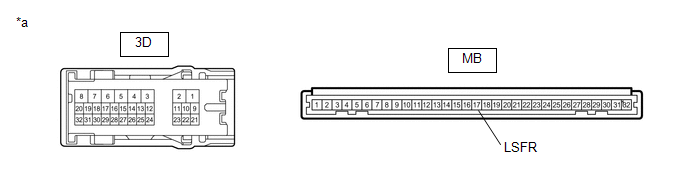
3D-12 - MB-17 (LSFR) |
Always |
Below 1 Ω |
| OK | |
REPLACE MAIN BODY ECU (MULTIPLEX NETWORK BODY ECU)
|
| NG | |
REPLACE INSTRUMENT PANEL JUNCTION BLOCK ASSEMBLY
|
|
8. |
INSPECT REAR DOOR LOCK WITH MOTOR ASSEMBLY LH |
(a) Remove the rear door lock with motor assembly LH.
Click here
(b) Inspect the rear door lock with motor assembly LH.
Click here
OK:
Rear door lock with motor assembly LH is normal.
| NG | |
REPLACE REAR DOOR LOCK WITH MOTOR ASSEMBLY LH
|
|
|
9. |
CHECK HARNESS AND CONNECTOR (REAR DOOR LOCK WITH MOTOR ASSEMBLY LH - INSTRUMENT PANEL JUNCTION BLOCK ASSEMBLY AND BODY GROUND) |
(a) Disconnect the 3D instrument panel junction block assembly connector.
(b) Measure the resistance according to the value(s) in the table below.
Standard Resistance:
|
Tester Connection |
Condition |
Specified Condition |
|---|---|---|
|
L1-5 (LSSR) - 3D-14 |
Always |
Below 1 Ω |
|
L1-5 (LSSR) or 3D-14 - Body ground |
Always |
10 kΩ or higher |
|
L1-6 (E) - Body ground |
Always |
Below 1 Ω |
| NG | |
REPAIR OR REPLACE HARNESS OR CONNECTOR |
|
|
10. |
INSPECT REAR DOOR LOCK WITH MOTOR ASSEMBLY RH |
(a) Remove the rear door lock with motor assembly RH.
Click here
(b) Inspect the rear door lock with motor assembly RH.
Click here
OK:
Rear door lock with motor assembly RH is normal.
| NG | |
REPLACE REAR DOOR LOCK WITH MOTOR ASSEMBLY RH
|
|
|
11. |
CHECK HARNESS AND CONNECTOR (REAR DOOR LOCK ASSEMBLY RH - INSTRUMENT PANEL JUNCTION BLOCK ASSEMBLY AND BODY GROUND) |
(a) Measure the resistance according to the value(s) in the table below.
Standard Resistance:
|
Tester Connection |
Condition |
Specified Condition |
|---|---|---|
|
K1-9 (LSSR) - 3D-14 |
Always |
Below 1 Ω |
|
K1-9 (LSSR) or 3D-14 - Body ground |
Always |
10 kΩ or higher |
|
K1-10 (E) - Body ground |
Always |
Below 1 Ω |
| NG | |
REPAIR OR REPLACE HARNESS OR CONNECTOR |
|
|
12. |
INSPECT INSTRUMENT PANEL JUNCTION BLOCK ASSEMBLY |
(a) Remove the instrument panel junction block assembly.
Click here
(b) Remove the main body ECU (multiplex network body ECU) from the instrument panel junction block assembly.
Click here
(c) Measure the resistance according to the value(s) in the table below.
|
*a |
Component without harness connected (Instrument Panel Junction Block Assembly) |
- |
- |
Standard Resistance:
|
Tester Connection |
Condition |
Specified Condition |
|---|---|---|
|
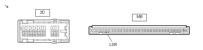
3D-14 - MB-5 (LSR) |
Always |
Below 1 Ω |
| OK | |
REPLACE MAIN BODY ECU (MULTIPLEX NETWORK BODY ECU)
|
| NG | |
REPLACE INSTRUMENT PANEL JUNCTION BLOCK ASSEMBLY
|
 Engine Switch Illumination Circuit
DESCRIPTION
The illuminated entry system controls the engine switch illumination.
WIRING DIAGRAM
CAUTION / NOTICE / HINT
NOTICE:
Before replacing the certification ECU (smart key ECU assembly), ...
 Luggage Compartment Room Light
Components
COMPONENTS
ILLUSTRATION
*1
NO. 1 LUGGAGE COMPARTMENT LIGHT ASSEMBLY
-
-
ILLUSTRATION
*1
LUGGAGE COMPART ...
Other materials:
Toyota CH-R Service Manual > Navigation System: Does not Play even after Bluetooth Audio Mode is Selected
CAUTION / NOTICE / HINT
NOTICE:
Depending on the parts that are replaced during vehicle inspection or
maintenance, performing initialization, registration or calibration may
be needed. Refer to Precaution for Navigation System.
Click here
When replacing the radio ...
Toyota CH-R Service Manual > Rear Door Window Frame Moulding: Installation
INSTALLATION
CAUTION / NOTICE / HINT
HINT:
Use the same procedure for the RH side and LH side.
The following procedure is for the LH side.
PROCEDURE
1. INSTALL REAR DOOR REAR WINDOW FRAME MOULDING
(a) Using an air riveter or hand riveter with a nose piece, install the rear
...
Toyota C-HR (AX20) 2023-2026 Owner's Manual
Toyota CH-R Owners Manual
- For safety and security
- Instrument cluster
- Operation of each component
- Driving
- Interior features
- Maintenance and care
- When trouble arises
- Vehicle specifications
- For owners
Toyota CH-R Service Manual
- Introduction
- Maintenance
- Audio / Video
- Cellular Communication
- Navigation / Multi Info Display
- Park Assist / Monitoring
- Brake (front)
- Brake (rear)
- Brake Control / Dynamic Control Systems
- Brake System (other)
- Parking Brake
- Axle And Differential
- Drive Shaft / Propeller Shaft
- K114 Cvt
- 3zr-fae Battery / Charging
- Networking
- Power Distribution
- Power Assist Systems
- Steering Column
- Steering Gear / Linkage
- Alignment / Handling Diagnosis
- Front Suspension
- Rear Suspension
- Tire / Wheel
- Tire Pressure Monitoring
- Door / Hatch
- Exterior Panels / Trim
- Horn
- Lighting (ext)
- Mirror (ext)
- Window / Glass
- Wiper / Washer
- Door Lock
- Heating / Air Conditioning
- Interior Panels / Trim
- Lighting (int)
- Meter / Gauge / Display
- Mirror (int)
- Power Outlets (int)
- Pre-collision
- Seat
- Seat Belt
- Supplemental Restraint Systems
- Theft Deterrent / Keyless Entry

0.007