Toyota CH-R Service Manual: Diagnosis System
DIAGNOSIS SYSTEM
CHECK FOR INSTALLED SYSTEMS (ECUS AND SENSORS) THAT USE CAN COMMUNICATION
(a) The systems (ECUs and sensors) that use CAN communication vary depending on the vehicle and optional equipment. Check which systems (ECUs and sensors) are installed to the vehicle.
(1) Techstream display and installed systems
HINT:
The names of ECUs and sensors shown on the Techstream display may differ from those shown in DTC Table by ECU.
|
Connected to |
Code |
ECU/Sensor Name |
Techstream Display |
Applicability |
|---|---|---|---|---|
|
- |
CGW |
Central gateway ECU (network gateway ECU) |
- |
Installed on all vehicles |
|
- |
DLC3 |
DLC3 |
- |
Installed on all vehicles |
|
Bus 1 |
BSM |
Blind spot monitor sensor LH |
Blind Spot Monitor Master |
Vehicles with Blind Spot Monitor System |
|
F-CAM |
Forward recognition camera |
Front Camera Module |
Vehicles with Toyota Safety Sense P |
|
|
F-MR |
Millimeter wave radar sensor assembly |
Front Radar |
Vehicles with Toyota Safety Sense P |
|
|
Bus 2 |
ENG |
ECM |
ECM (Engine) |
Installed on all vehicles |
|
Bus 3 |
AV |
Radio and display receiver assembly |
Display and Navigation (AVN) |
Vehicles with Radio and Display Type |
|
DCM |
DCM (Telematics transceiver) |
DCM |
Vehicles with Telematics Transceiver |
|
|
Bus 4 |
STR |
Steering sensor |
Spiral cable (Steering Angle Sensor) |
Installed on all vehicles |
|
EPS |
Power steering ECU assembly |
Power Steering (EPS) |
Installed on all vehicles |
|
|
BRK |
Brake actuator assembly |
Skid Control (ABS/VSC/TRAC) |
Installed on all vehicles |
|
|
OCS |
Occupant detection ECU |
Occupant Detection |
Vehicles with Occupant Detection ECU |
|
|
SRS |
Airbag sensor assembly |
Airbag |
Installed on all vehicles |
|
|
Bus 5 |
A/C |
Air conditioning amplifier assembly |
Air Conditioning Amplifier |
Installed on all vehicles |
|
SMT |
Certification ECU (smart key ECU assembly) |
Certification (Smart) |
Vehicles with Smart Key System |
|
|
MB |
Main body ECU (multiplex network body ECU) |
Main Body |
Installed on all vehicles |
|
|
MET |
Combination meter assembly |
Combination Meter |
Installed on all vehicles |
|
|
LIT |
Headlight ECU sub-assembly LH |
Headlight swivel (AFS) |
Vehicles with LED Headlight |
NOTICE:
The following communication bus check screen is provided only as an example. This screen differs from the actual screen for this vehicle.
Description of "Communication Bus Check" Screen
HINT:
The ECUs and sensors that are normally connected to the CAN communication system are displayed on the Techstream.
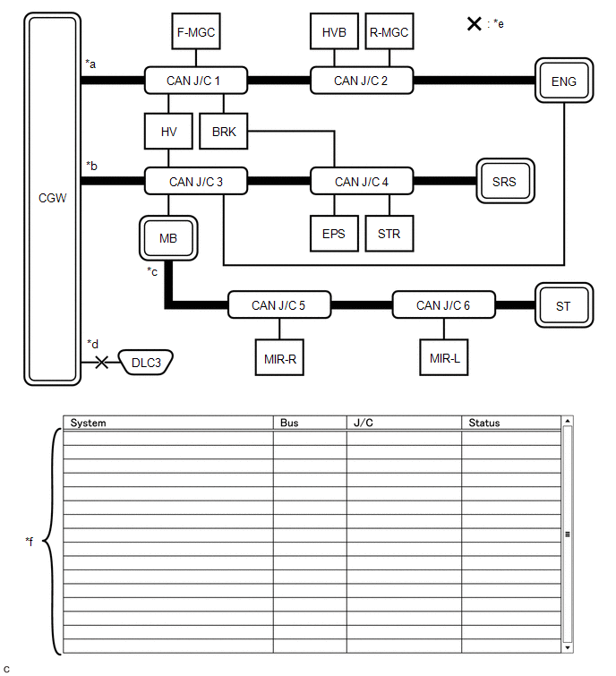
(a) Select "Communication Bus Check" on the menu screen of the Techstream.
CAN Bus CheckHINT:
If items are not selected correctly in the vehicle specification pop up screen, the name of the CAN junction connector to which the ECUs or sensors are connected may not be displayed on the "Communication Bus Check" screen.
(b) Confirm that the "Communication Bus Check" screen is displayed and the ECUs and sensors that are normally connected to the CAN communication system are displayed.
HINT:
- Even if an ECU or sensor that is connected to a bus that is monitored by a bus monitoring ECU (gateway function equipped ECU) is not communicating, it will remain displayed on the "Communication Bus Check" screen.
- When an ECU or sensor that is connected to a bus that is not monitored by a bus monitoring ECU (gateway function equipped ECU) is not displayed on the "Communication Bus Check" screen, it means that it is not communicating.
(c) The default display setting selected on the combo box is ALL. When checking for ECUs or sensors for a specific bus, choose the bus from the drop down list. ALL, each bus, each sub bus and Central Gateway are listed in the drop down list.
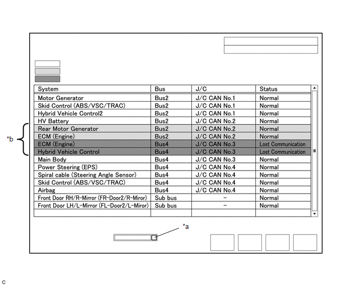
|
*a |
Combo box |
*b |
Background color is red or yellow |
|
Item |
Detail |
|---|---|
|
Combo box: ALL |
Displays all ECUs and sensors connected to the central bus and sub buses. |
|
Combo box: Bus |
Displays ECUs and sensors connected to the selected bus. |
|
Combo box: Sub bus |
Displays ECUs and sensors connected to the selected sub bus. |
|
Combo box: Central Gateway |
Displays all ECUs and sensors connected to the central bus. |
NOTICE:
- When using the combo box, it may be possible to select a sub bus from the drop down list that does not have any connected ECUs or sensors. This is not a malfunction and occurs when there is no optional device connected to a sub bus which is monitored by a sub bus monitoring ECU (gateway function equipped ECU).
- In the drop down list, all sub buses applicable to the model are displayed
(e.g. LIN communication sub buses are also displayed). For information on
sub buses necessary to diagnose the CAN communication system, refer to System
Diagram.
Click here
.gif)
HINT:
The background color of an ECU or sensor changes according to its connection status as indicated in the following table.
Description of "Communication Bus Check" Screen|
Bus Type |
Background Color |
Connection Status |
|---|---|---|
|
Bus |
White |
Communication has been normal. |
|
Yellow |
Communication stop occurred at least once since the start of the CAN bus check, but communication is currently occurring (unstable communication). |
|
|
Red |
Currently not communicating (either of the following):
|
|
|
Not displayed |
Either of the following:
|
|
|
Sub bus with a gateway function equipped ECU that does not memorize connected ECUs or sensors*2 |
White |
Communication has been normal since the start of the CAN bus check. |
|
Yellow |
Communication stop occurred at least once since the start of the CAN bus check, but communication is currently occurring (unstable communication). |
|
|
Red |
Communication occurred at least once since the start of the CAN bus check, but is currently not occurring. |
|
|
Not displayed |
Communication stop has continued since the start of the CAN bus check.*1 |
|
|
Sub bus with a gateway function equipped ECU that memorizes connected ECUs and sensors*3 |
White |
Communication has been normal. |
|
Yellow |
Communication stop occurred at least once since the start of the CAN bus check, but communication is currently occurring (unstable communication). |
|
|
Red |
Currently not communicating (either of the following):
|
|
|
Not displayed |
Either of the following:
|
- Gateway function equipped ECUs relay signals between ECUs and sensors connected to different buses.
- *1: An ECU or sensor is installed to the vehicle but is not displayed on the "Communication Bus Check" screen.
- *2: The gateway function equipped ECU does not memorize ECUs and sensors connected to its respective sub bus.
- *3: The gateway function equipped ECU memorizes ECUs and sensors connected to its respective sub bus.
- *4: When the central gateway ECU (network gateway ECU) has an internal malfunction or cannot communicate with the Techstream, the name of buses, sub buses, ECUs and sensors will not be displayed.
- *5: When no ECUs or sensors are connected to a bus, the message "There is no system found on the communication Bus." will be displayed.
- *6: When a gateway function equipped ECU cannot communicate with the central gateway ECU (network gateway ECU), the name of sub buses and ECUs or sensors connected to the sub bus will not be displayed.
- *7: When no ECUs or sensors are connected to the sub bus, the message "There is no system found on the communication Bus." will be displayed.
- If there is no communication between the Techstream and the vehicle, or no ECUs or sensors are displayed as connected, check the central gateway ECU (network gateway ECU) and diagnosis bus (the bus that connects the DLC3 to the central gateway ECU (network gateway ECU)) for malfunctions.
(d) Monitor the screen for any ECU or sensor connection status changes for a period of 2 minutes.
HINT:
- If an open occurs in one of the wires of a CAN branch line, it may interfere with the communication of other ECUs or sensors resulting in an incorrect state being displayed.
- If the connection status changes intermittently during the inspection, repair the open in the branch line of the ECU or sensor that is not communicating, and then perform Communication Bus Check again.
NOTICE:
The following communication bus check screen is provided only as an example. This screen differs from the actual screen for this vehicle.
Description of "Communication Bus Check (Detail)" Screen
HINT:
The communication error history of ECUs or sensors which have communication error history can be displayed on the "Communication Bus Check (Detail)" screen.
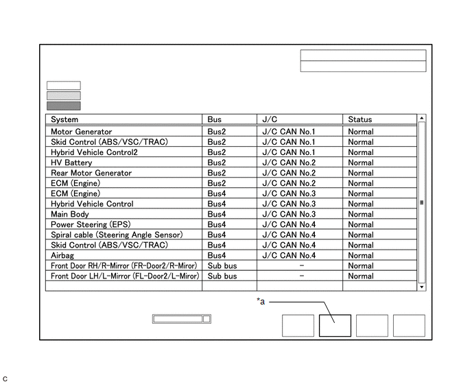
(a) Select "Communication Bus Check" on the menu screen of the Techstream.
CAN Bus CheckHINT:
If items are not selected correctly in the vehicle specification pop up screen, the name of the CAN junction connector to which the ECUs or sensors are connected may not be displayed on the "Communication Bus Check" screen.
(b) Select "Detail" on the "Communication Bus Check" screen.

|
*a |
Communication Bus Check (Detail) |
- |
- |
(c) Confirm that the "Communication Bus Check (Detail)" screen is displayed and the communication error history of the ECUs or sensors up to present is displayed.
HINT:
- Lost Communication Time and Lost Communication Trip are only displayed for the central bus.
- Lost Communication Time and Lost Communication Trip are not displayed for sub buses.
(d) The default display setting selected on the combo box is ALL. When checking for ECUs or sensors for a specific bus, choose the bus from the drop down list. ALL, each bus, each sub bus and Central Gateway are listed in the drop down list.
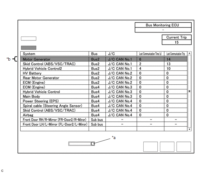
|
*a |
Combo box |
*b |
Background color is red |
|
Item |
Detail |
|---|---|
|
Combo box: ALL |
Displays all ECUs and sensors connected to the central bus and sub buses. |
|
Combo box: Bus |
Displays ECUs and sensors connected to the selected bus. |
|
Combo box: Sub bus |
Displays ECUs and sensors connected to the selected sub bus. |
|
Combo box: Central Gateway |
Displays all ECUs and sensors connected to the central bus. |
|
Bus Monitoring ECU |
Displays the gateway function equipped ECU which monitors the selected bus or sub bus. |
|
Current Trip |
Displays the total number of trips up to now* |
|
Lost Communication Time(s) |
Displays the longest period of time in seconds that the ECU or sensor connected to the central bus was not communicating. |
|
Lost Communication Trip |
Displays the trip in which the longest period of time that the ECU or sensor connected to the central bus was not communicating occurred. |
- *: If the component has been replaced with a new one, the total number of trips after the replacement is displayed.
NOTICE:
- The Lost Communication Time column displays the longest period of time in seconds that the central gateway ECU (network gateway ECU) detected a communication stop in the respective ECU or sensor.
- The Lost Communication Trip column displays the trip in which the central gateway ECU (network gateway ECU) detected the longest communication stop in the respective ECU or sensor.
- When using the combo box, it may be possible to select a sub bus from the drop down list that does not have any connected ECUs or sensors. This is not a malfunction and occurs when there is no optional device connected to a sub bus which is monitored by a sub bus monitoring ECU (gateway function equipped ECU).
- In the drop down list, all sub buses applicable to the model are displayed
(e.g. LIN communication sub buses are also displayed). For information on
sub buses necessary to diagnose CAN communication system, refer to the System
Diagram.
Click here
HINT:
The background color of an ECU or sensor changes according to its connection status as indicated in the following table.
Description of "Communication Bus Check (Detail)" Screen|
Bus Type |
Background Color |
Connection Status |
|---|---|---|
|
Bus |
White |
Either of the following:
|
|
Red |
Lost Communication Time is 6 seconds or more. |
|
|
Not displayed |
Either of the following:
|
|
|
Sub bus |
White |
Lost Communication Time is displayed as "-". |
|
Not displayed |
Either of the following:
|
- If there is no communication between the Techstream and the vehicle, or no ECUs or sensors are displayed as connected, check the central gateway ECU (network gateway ECU) and diagnosis bus (the bus that connects the DLC3 to the central gateway ECU (network gateway ECU)) for malfunctions.
- Lost Communication Time and Lost Communication Trip are not displayed for sub buses.
- *1: When the central gateway ECU (network gateway ECU) has an internal malfunction or cannot communicate with the Techstream, the name of buses, sub buses, ECUs and sensors will not be displayed.
- *2: When no ECUs or sensors are connected to a bus, the message "There is no system found on the communication Bus." will be displayed.
- *3: When a gateway function equipped ECU cannot communicate with the central gateway ECU (network gateway ECU), the name of sub buses and ECUs or sensors connected to the sub bus will not be displayed.
- *4: When no ECUs or sensors are connected to the sub bus, the message "There is no system found on the communication Bus." will be displayed.
Communication Bus Check (Communication Malfunction Check)
HINT:
DTCs related to CAN communication are displayed for each ECU on the Techstream.
(a) Select "Communication Bus Check" on the menu screen of the Techstream.
CAN Bus Check(b) Select "Communication Malfunction Check" on the "Communication Bus Check" screen.
|
*a |
Communication Malfunction Check |
- |
- |
(c) Confirm that the "Communication Malfunction Check" screen is displayed and CAN communication DTCs for each ECU are displayed.
HINT:
When there are no CAN communication DTCs stored, no DTCs will be displayed.
How to Use "Communication Bus Check" Screen in Inspection
NOTICE:
The following CAN bus wiring diagram or communication bus check screen is provided only as an example. This wiring diagram or screen differs from the actual one for this vehicle.
HINT:
- If the CAN communication system is currently malfunctioning, it is recommended to use Communication Bus Check rather than Communication DTCs for determining the suspected area.
- Turn the ignition switch to ON, or perform the necessary operations to reproduce the problem symptom, select "Communication Bus Check" and wait approximately 2 minutes. Check the communication status of each ECU or sensor on the screen while performing this operation.
(a) If the CAN communication system is currently malfunctioning, determine the suspected area through Communication Bus Check as follows:
Problem Symptoms Table|
Problem Symptom Pattern |
Display on Communication Bus Check Screen |
Suspected Area |
|---|---|---|
|
A |
Almost all of the ECUs and sensors connected to the malfunctioning CAN bus are displayed as not communicating on the "Communication Bus Check" screen. |
|
|
B |
ECUs or sensors farther from the central gateway ECU (network gateway ECU) than the open in the wires are displayed as not communicating on the "Communication Bus Check" screen. |
Open in both wires of a main bus line in the central bus |
|
C |
One ECU or sensor is displayed as not communicating on the "Communication Bus Check" screen. |
|
|
D |
No ECUs or sensors are displayed on the "Communication Bus Check" screen. |
|
|
E |
One ECU or sensor is displayed as not communicating in multiple buses on the "Communication Bus Check" screen. |
|
|
F |
Some ECUs or sensors are displayed as not communicating in the central bus and other ECUs or sensors are displayed as not communicating in a sub bus. |
|
|
G |
A gateway function equipped ECU is displayed as not communicating in the central bus and ECUs and sensors connected to its respective sub bus are not displayed. |
|
|
H |
One ECU or sensor is displayed as not communicating in a sub bus on the "Communication Bus Check" screen. |
|
|
I |
ECUs or sensors farther from the sub bus monitoring ECU (gateway function equipped ECU) than the open in the wires are displayed as not communicating on the "Communication Bus Check" screen. |
Open in both wires of a main bus line in a sub bus |
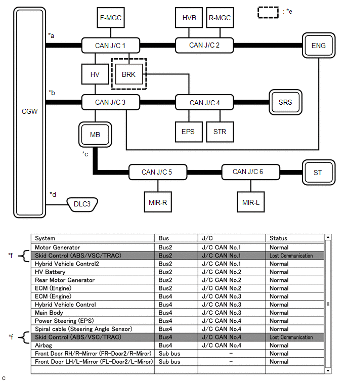
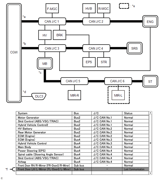
(b) Problem Symptom Pattern A
|
Details of Malfunction |
|
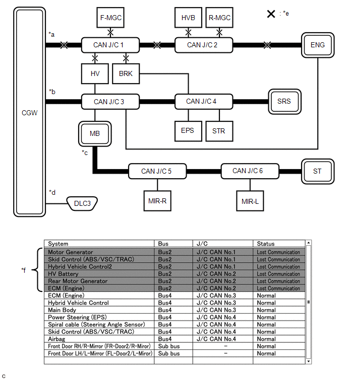
|
*a |
Bus 2 |
*b |
Bus 4 |
|
*c |
Sub bus |
*d |
Diagnosis bus |
|
*e |
Location of malfunction |
*f |
Background color is red |
HINT:
- Due to the malfunction, almost all of the ECUs and sensors connected to Bus 2 will be displayed as not communicating and their background color will be red.
- The malfunction in Bus 2 will not affect the other buses.
- The malfunctioning part can be determined by inspecting for an open in the main bus line, a short between bus lines or a short to +B or ground.
- Make sure to perform the inspection to measure resistances of buses to determine the cause of the malfunction.
|
Details of Malfunction |
|
|
*a |
Bus 2 |
*b |
Bus 4 |
|
*c |
Sub bus |
*d |
Diagnosis bus |
|
*e |
Location of malfunction |
*f |
Background color is red |
|
*g |
Not displayed |
- |
- |
HINT:
- Due to the malfunction, almost all of the ECUs and sensors connected to Bus 4 will be displayed as not communicating and their background color will be red.
- The malfunction will not affect the other buses of the central bus. However, the sub bus connected to Bus 4 is likely to be affected. The gateway function equipped ECU connected to Bus 4 will not communicate and consequently the sub bus and its respective ECUs or sensors monitored by the gateway function equipped ECU (sub bus monitoring ECU) will not be displayed, indicating that the gateway function equipped ECU is not communicating with the central gateway ECU (network gateway ECU).
- The malfunctioning part can be determined by inspecting for an open in the main bus line, a short between bus lines or a short to +B or ground.
- Make sure to perform the inspection to measure resistances of buses to determine the cause of the malfunction.
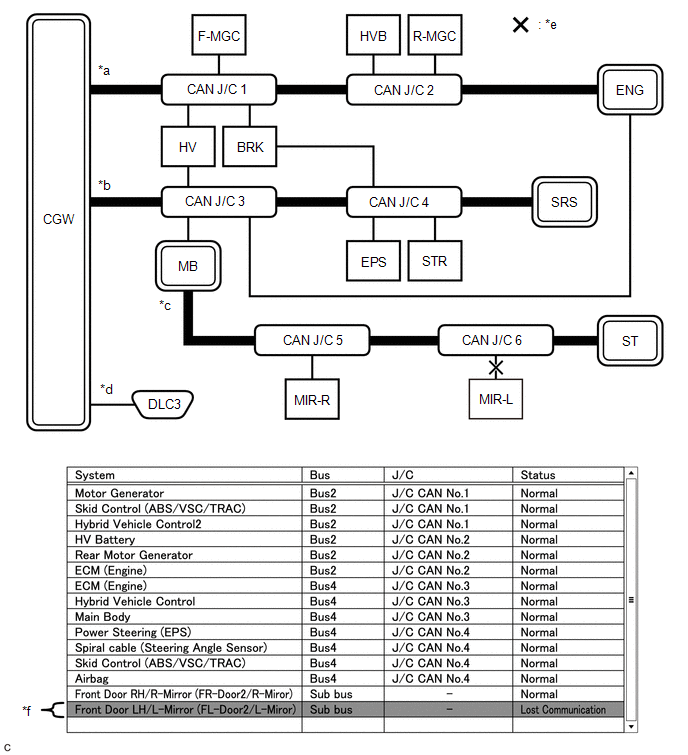
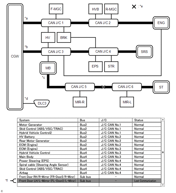
(c) Problem Symptom Pattern B
|
Details of Malfunction |
Open in both wires of the main bus line between the CGW and No. 1 CAN junction connector in Bus 2 |
|
*a |
Bus 2 |
*b |
Bus 4 |
|
*c |
Sub bus |
*d |
Diagnosis bus |
|
*e |
Location of malfunction |
*f |
Background color is red |
HINT:
- Due to the malfunction, almost all of the ECUs and sensors connected to Bus 2 will be displayed as not communicating and their background color will be red.
- The malfunction in Bus 2 will not affect the other buses.
- The malfunctioning part can be determined by inspecting for an open in the main bus line.
- Make sure to perform the inspection to measure resistances of buses to determine the cause of the malfunction.
|
Details of Malfunction |
Open in both wires of the main bus line between the No. 1 CAN junction connector and No. 2 CAN junction connector in Bus 2 |
|
*a |
Bus 2 |
*b |
Bus 4 |
|
*c |
Sub bus |
*d |
Diagnosis bus |
|
*e |
Location of malfunction |
*f |
Background color is red |
HINT:
- Due to the malfunction, ECUs or sensors farther from the CGW than the open in the wires will be displayed as not communicating and their background color will be red.
- The malfunction in Bus 2 will not affect the other buses.
- The malfunctioning part can be determined by inspecting for an open in the main bus line.
- Make sure to perform the inspection to measure resistances of buses to determine the cause of the malfunction.
|
Details of Malfunction |
Open in both wires of the main bus line between the No. 2 CAN junction connector and ENG in Bus 2 |
|
*a |
Bus 2 |
*b |
Bus 4 |
|
*c |
Sub bus |
*d |
Diagnosis bus |
|
*e |
Location of malfunction |
*f |
Background color is red |
|
*g |
Pattern 1 |
*h |
Pattern 2 |
HINT:
- Even when the same part of the main bus line is open, depending on internal electrical noise which changes according to the position of the open in the line, the information displayed on the "Communication Bus Check" screen may differ.
- In pattern 2, the information displayed may be the same as when there is an open in both wires in the main bus line between the No. 1 CAN junction connector and No. 2 CAN junction connector, which may make it difficult to determine the malfunctioning part.
- The malfunction in Bus 2 will not affect the other buses.
- Make sure to perform the inspection to measure resistances of buses to determine the cause of the malfunction.
(d) Problem Symptom Pattern C
|
Details of Malfunction |
Open in both wires of the branch line connected to F-MGC in Bus 2 |
|
*a |
Bus 2 |
*b |
Bus 4 |
|
*c |
Sub bus |
*d |
Diagnosis bus |
|
*e |
Location of malfunction |
*f |
Background color is red |
HINT:
The information displayed on the "Communication Bus Check" screen will be the same for an open in both wires of a branch line, an internal malfunction of an ECU or sensor or a malfunction in the power supplied to an ECU or sensor. In this example, the background color of the malfunctioning ECU or sensor will be red.
|
Details of Malfunction |
|
|
*a |
Bus 2 |
*b |
Bus 4 |
|
*c |
Sub bus |
*d |
Diagnosis bus |
|
*e |
Location of malfunction |
*f |
Background color is red |
HINT:
The information displayed on the "Communication Bus Check" screen will be the same for an open in both wires of a branch line, an internal malfunction of an ECU or sensor or a malfunction in the power supplied to an ECU or sensor. In this example, the background color of the malfunctioning ECU or sensor will be red.
|
Details of Malfunction |
Open in both wires of the branch line connected to ENG in Bus 4 |
|
*a |
Bus 2 |
*b |
Bus 4 |
|
*c |
Sub bus |
*d |
Diagnosis bus |
|
*e |
Location of malfunction |
*f |
Background color is red |
HINT:
- The malfunction in Bus 4 will not affect the other buses.
- Due to the malfunction, although ENG is communicating normally with CGW via Bus 2, it is not communicating with CGW via Bus 4. Consequently, it will be displayed as not communicating in Bus 4.
(e) Problem Symptom Pattern D
|
Details of Malfunction |
|
|
*a |
Bus 2 |
*b |
Bus 4 |
|
*c |
Sub bus |
*d |
Diagnosis bus |
|
*e |
Location of malfunction |
*f |
Not displayed |
HINT:
When there is no communication between the Techstream and the vehicle, no ECUs or sensors will be displayed.
|
Details of Malfunction |
Open in both wires of the branch lines in the diagnosis bus |
|
*a |
Bus 2 |
*b |
Bus 4 |
|
*c |
Sub bus |
*d |
Diagnosis bus |
|
*e |
Location of malfunction |
*f |
Not displayed |
HINT:
When there is no communication between the Techstream and the vehicle, no ECUs or sensors will be displayed.
(f) Problem Symptom Pattern E
|
Details of Malfunction |
|
|
*a |
Bus 2 |
*b |
Bus 4 |
|
*c |
Sub bus |
*d |
Diagnosis bus |
|
*e |
Location of malfunction |
*f |
Background color is red |
HINT:
The information displayed on the "Communication Bus Check" screen will be the same for an internal malfunction of an ECU or sensor, or a malfunction in the power supplied to an ECU or sensor.
Due to the malfunction, BRK is not communicating with the CGW via both Bus 2 and Bus 4. Consequently, the background color of BRK will be red for both Bus 2 and Bus 4.
(g) Problem Symptom Pattern F
|
Details of Malfunction |
|
|
*a |
Bus 2 |
*b |
Bus 4 |
|
*c |
Sub bus |
*d |
Diagnosis bus |
|
*e |
Location of malfunction |
*f |
Background color is red |
|
*g |
Background color intermittently becomes yellow or red |
*h |
Not displayed or background color is yellow or red |
HINT:
- In the "Communication Bus check" screen shown in the illustration, electrical noise in the CAN bus caused by an open in a wire in the branch line connected to HV interferes with the communication of MB causing unstable communication. Also, since MB is a gateway function equipped ECU, communication of ECUs connected to its respective sub bus will also be unstable.
- In the "Communication Bus Check" screen shown in the illustration, because the background color of HV is red, it is suspected that HV is the most likely cause of the malfunction. Therefore, it is suspected that HV is not communicating.
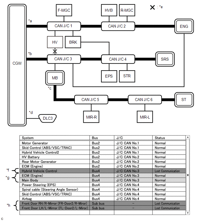
(h) Problem Symptom Pattern G
|
Details of Malfunction |
|
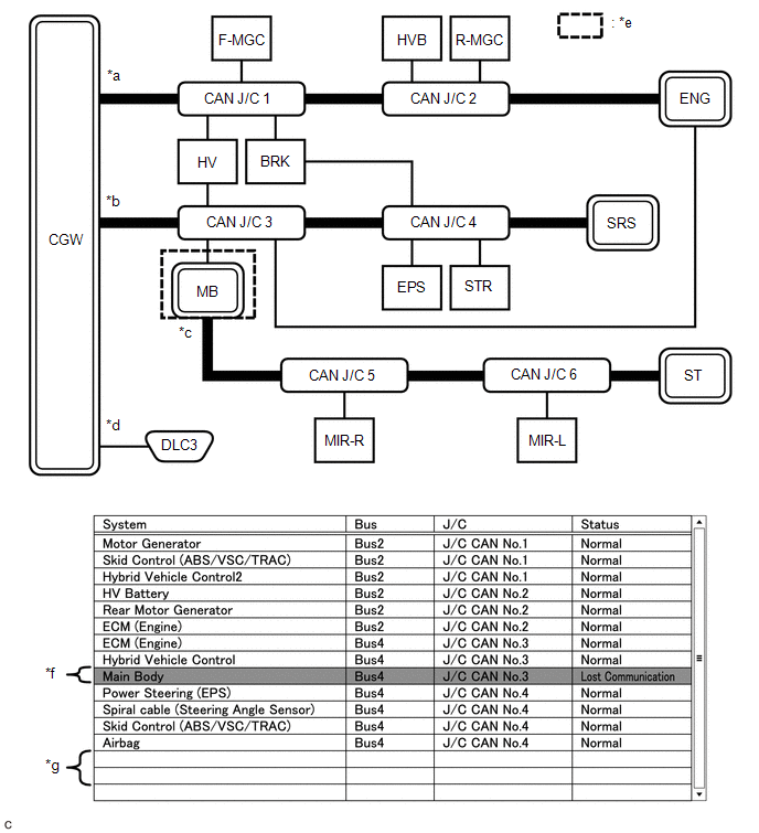
|
*a |
Bus 2 |
*b |
Bus 4 |
|
*c |
Sub bus |
*d |
Diagnosis bus |
|
*e |
Location of malfunction |
*f |
Background color is red |
|
*g |
Not displayed |
- |
- |
HINT:
- If there is a communication malfunction in a gateway function equipped ECU, ECUs connected to its respective sub bus will also be affected and will not be displayed.
- In the "Communication Bus Check" screen shown in the illustration, MB is a gateway function equipped ECU. Therefore, MB is suspected as not communicating.
(i) Problem Symptoms Pattern H
|
Details of Malfunction |
|
|
*a |
Bus 2 |
*b |
Bus 4 |
|
*c |
Sub bus |
*d |
Diagnosis bus |
|
*e |
Location of malfunction |
*f |
Background color is red |
HINT:
- The malfunction in the sub bus will not affect the other buses.
- When a gateway function equipped ECU memorizes ECUs and sensors connected to its respective sub bus and there is a communication malfunction in one of the ECUs or sensors, the background color of the ECU or sensor will change to red and the ECU or sensor will remain displayed.
- The information displayed on the "Communication Bus Check" screen will be the same for an open in both wires of a branch line, an internal malfunction of an ECU or sensor or a malfunction in the power supplied to an ECU or sensor.
|
Details of Malfunction |
Open in both wires of the branch line connected to MIR-L in the sub bus |
|
*a |
Bus 2 |
*b |
Bus 4 |
|
*c |
Sub bus |
*d |
Diagnosis bus |
|
*e |
Location of malfunction |
*f |
Background color is red |
HINT:
- The malfunction in the sub bus will not affect the other buses.
- When a gateway function equipped ECU memorizes ECUs and sensors connected to its respective sub bus and there is a communication malfunction in one of the ECUs or sensors, the background color of the ECU or sensor will change to red and the ECU or sensor will remain displayed.
- The information displayed on the "Communication Bus Check" screen will be the same for an open in both wires of a branch line, an internal malfunction of an ECU or sensor or a malfunction in the power supplied to an ECU or sensor.
(j) Problem Symptom Pattern I
|
Details of Malfunction |
Open in both wires of the main bus line in the sub bus |
|
*a |
Bus 2 |
*b |
Bus 4 |
|
*c |
Sub bus |
*d |
Diagnosis bus |
|
*e |
Location of malfunction |
*f |
Background color is red |
HINT:
Due to the malfunction, ECUs or sensors farther from the sub bus monitoring ECU (gateway function equipped ECU) than the open in the wires will be displayed as not communicating and their background color will be red.
How to Use "Communication Bus check (Detail)" Screen in Inspection
(a) If the CAN communication system is currently normal but has communication stop history, determine the malfunctioning part using Communication Bus Check (Detail) as follows:
NOTICE:
- The following CAN bus wiring diagram or communication bus check screen is provided only as an example. This wiring diagram or screen differs from the actual one for this vehicle.
- The Lost Communication Time column displays the longest period of time in seconds that the central gateway ECU (network gateway ECU) detected a communication stop in the respective ECU or sensor.
- The Lost Communication Trip column displays the trip in which the central gateway ECU (network gateway ECU) detected the longest communication stop in the respective ECU or sensor.
- When using the combo box, it may be possible to select a sub bus from the drop down list that does not have any connected ECUs or sensors. This is not a malfunction and occurs when there is no optional device connected to a sub bus which is monitored by a sub bus monitoring ECU (gateway function equipped ECU).
- In the drop down list, all sub buses applicable to the model are displayed
(e.g. LIN communication sub buses are also displayed). For information on
sub buses necessary to diagnose CAN communication system, refer to the System
Diagram.
Click here
HINT:
- If the CAN communication system is currently malfunctioning, it is recommended to use Communication Bus Check rather than Communication Bus Check (Detail) for determining the suspected area.
- The communication error history of ECUs or sensors which have communication error history can be displayed on the "Communication Bus Check (Detail)" screen.
- Lost Communication Time and Lost Communication Trip are only displayed for the central bus.
- Lost Communication Time and Lost Communication Trip are not displayed for sub buses.
(b) If there is an ECU or sensor displayed with a red background on the "Communication Bus Check (Detail)" screen to indicate that it was not communicating, it is suspected that the ECU or sensor was not communicating.
|
Details of Malfunction |
Past malfunction in the wire harness or power supplied to F-MGC in Bus 2 |
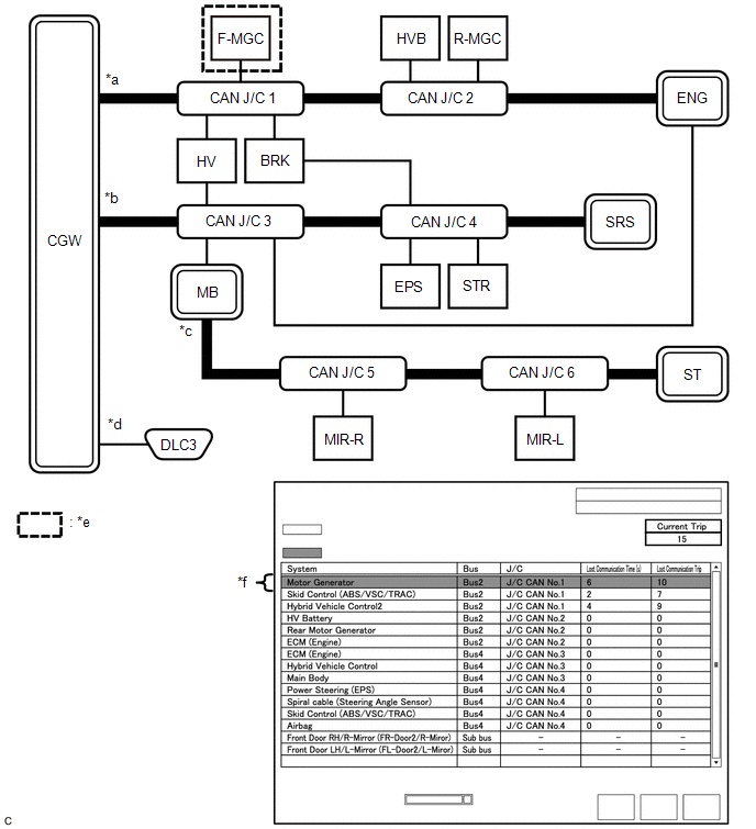
|
*a |
Bus 2 |
*b |
Bus 4 |
|
*c |
Sub bus |
*d |
Diagnosis bus |
|
*e |
Location of malfunction |
*f |
Background color is red |
|
Bus Type |
Background Color |
Connection Status |
|---|---|---|
|
Bus |
White |
Either of the following:
|
|
Red |
Lost Communication Time is 6 seconds or more. |
|
|
Not displayed |
Either of the following:
|
|
|
Sub bus |
White |
Lost Communication Time is displayed as "-". |
|
Not displayed |
Either of the following:
|
HINT:
- Check the values of Lost Communication Trip and Current Trip for the ECUs or sensors that have a red background color.
- If the values of Lost Communication Trip and Current Trip are the same for an ECU or sensor, the ECU or sensor is currently not communicating. In this case, it is recommended to use Communication Bus Check rather than Communication Bus Check (Detail) for determining the suspected area.
- In the "Communication Bus Check (Detail)" screen shown in the illustration, F-MGC had a communication malfunction in the 10th trip. Thus, it is suspected that F-MGC was not communicating.
- *1: When the central gateway ECU (network gateway ECU) has an internal malfunction or cannot communicate with the Techstream, the name of buses, sub buses, ECUs and sensors will not be displayed.
- *2: When no ECUs or sensors are connected to a bus, the message "There is no system found on the communication Bus." will be displayed.
- *3: When a gateway function equipped ECU cannot communicate with the central gateway ECU (network gateway ECU), the name of sub buses and ECUs or sensors connected to the sub bus will not be displayed.
- *4: When no ECUs or sensors are connected to the sub bus, the message "There is no system found on the communication Bus." will be displayed.
DTC TABLE BY ECU
HINT:
- In the CAN communication system, the CAN communication DTCs of each ECU can be displayed using the Techstream.
- If CAN communication system DTCs are output, the malfunction cannot
be determined only by the DTCs. Perform troubleshooting according to How
to Proceed with Troubleshooting.
Click here
- If there is a malfunction currently, DTCs can be checked by performing steps in the DTC check procedure.
(a) ECM / Techstream Display "Engine and ECT"
Powertrain > Engine and ECT > Trouble CodesHINT:
- This ECU uses the CAN communication system for DTC communication.
- *1: Refer to SFI System.
w/ Canister Pump Module: Click here
w/o Canister Pump Module: Click here
|
DTC |
Detection Item |
DTC Detection Condition |
DTC Detection Pre-condition |
DTC Check Procedure |
Warning Displayed |
DTC Storage Method |
|
|---|---|---|---|---|---|---|---|
|
Indication in Meter |
Multi-information Display |
||||||
|
U011B*1 |
Lost Communication with Rocker Arm Control Module "A" |
The ECM does not receive data from the continuously variable valve lift controller assembly for approximately 1 second or more. |
Both conditions are met:
|
Turn the ignition switch ON and wait for at least approximately 2 seconds. |
MIL illuminates. |
- |
DTC is stored until it is cleared using the Techstream. |
|
U0124 |
Lost Communication with Lateral Acceleration Sensor Module |
The ECM does not receive data from the airbag sensor assembly for approximately 3 seconds or more. |
Both conditions are met:
|
Turn the ignition switch ON and wait for at least approximately 13 seconds. |
MIL illuminates. |
- |
DTC is stored until it is cleared using the Techstream. |
|
U0129 |
Lost Communication with Brake System Control Module |
The ECM does not receive data from the brake actuator assembly for approximately 3 seconds or more. |
Both conditions are met:
|
Turn the ignition switch ON and wait for at least approximately 13 seconds. |
MIL illuminates. |
- |
DTC is stored until it is cleared using the Techstream. |
(b) Brake Actuator Assembly / Techstream Display "ABS/VSC/TRAC/EPB"
Chassis > ABS/VSC/TRAC/EPB > Trouble CodesHINT:
This ECU uses the CAN communication system for DTC communication.
|
DTC |
Detection Item |
DTC Detection Condition |
DTC Detection Pre-condition |
DTC Check Procedure |
Warning Displayed |
DTC Storage Method |
|
|---|---|---|---|---|---|---|---|
|
Indication in Meter |
Multi-information Display |
||||||
|
U0073 |
Control Module Communication Bus Off |
A communication error (bus-off status) occurs consecutively for approximately 1 second or more. |
Both conditions are met:
|
Turn the ignition switch ON and wait for at least approximately 2 seconds. |
|
- |
DTC is stored until it is cleared using the Techstream. |
|
U0100 |
Lost Communication with ECM/PCM "A" |
The brake actuator assembly does not receive data from the ECM for approximately 1 second or more. |
All conditions are met:
|
Drive the vehicle at a speed of 6 km/h (4 mph) or more for approximately 2 seconds or more. |
|
- |
DTC is stored until it is cleared using the Techstream. |
|
U0123 |
Lost Communication with Yaw Rate Sensor Module |
The brake actuator assembly does not receive data from the airbag sensor assembly for approximately 1 second or more. |
All conditions are met:
|
Drive the vehicle at a speed of 6 km/h (4 mph) or more for approximately 2 seconds or more. |
|
- |
DTC is stored until it is cleared using the Techstream. |
|
U0126 |
Lost Communication with Steering Angle Sensor Module |
The brake actuator assembly does not receive data from the steering sensor for approximately 1 second or more. |
All conditions are met:
|
Drive the vehicle at a speed of 6 km/h (4 mph) or more for approximately 2 seconds or more. |
|
- |
DTC is stored until it is cleared using the Techstream. |
|
U0142 |
Lost Communication with Body Control Module "B" |
The brake actuator assembly does not receive data from the main body ECU (multiplex network body ECU) approximately 1 second or more. |
Both conditions are met:
|
Turn the ignition switch ON and wait for at least approximately 2 seconds. |
|
- |
DTC is stored until it is cleared using the Techstream. |
(c) Power Steering ECU Assembly / Techstream Display "EMPS"
Chassis > EMPS > Trouble CodesHINT:
This ECU uses the CAN communication system for DTC communication.
|
DTC |
Detection Item |
DTC Detection Condition |
DTC Detection Pre-condition |
DTC Check Procedure |
Warning Displayed |
DTC Storage Method |
|
|---|---|---|---|---|---|---|---|
|
Indication in Meter |
Multi-information Display |
||||||
|
U0100 |
Lost Communication with ECM/PCM "A" |
The power steering ECU assembly does not receive data from the ECM for approximately 5 minutes or more. |
All conditions are met:
|
Drive the vehicle at a speed of 20 km/h (12 mph) or more for approximately 5 minutes or more. |
- |
- |
DTC remains stored only while malfunction is occurring. |
|
U0129 |
Lost Communication with Brake System Control Module |
The power steering ECU assembly does not receive data from the brake actuator assembly for approximately 3 seconds or more. |
Both conditions are met:
|
Turn the ignition switch ON and wait for at least approximately 6 seconds. |
EPS warning light illuminates. |
- |
DTC remains stored only while malfunction is occurring. |
|
U023A |
Lost Communication with Front Camera Module |
The power steering ECU assembly does not receive data from the forward recognition camera for approximately 2 seconds or more. |
Both conditions are met:
|
Turn the ignition switch ON and wait for at least approximately 5 seconds. |
- |
- |
DTC remains stored only while malfunction is occurring. |
(d) Main Body ECU (Multiplex Network Body ECU) / Techstream Display "Main Body"
Body Electrical > Main Body > Trouble CodesHINT:
This ECU uses the CAN communication system for DTC communication.
|
DTC |
Detection Item |
DTC Detection Condition |
DTC Detection Pre-condition |
DTC Check Procedure |
Warning Displayed |
DTC Storage Method |
|
|---|---|---|---|---|---|---|---|
|
Indication in Meter |
Multi-information Display |
||||||
|
U0100 |
Lost Communication with ECM/PCM "A" |
The main body ECU (multiplex network body ECU) does not receive data from the ECM for approximately 10 seconds or more. |
Both conditions are met:
|
Turn the ignition switch ON and wait for at least approximately 20 seconds. |
- |
- |
DTC is stored until it is cleared using the Techstream. |
|
U0101 |
Lost Communication with TCM |
The main body ECU (multiplex network body ECU) does not receive data from the ECM for approximately 10 seconds or more. |
Both conditions are met:
|
Turn the ignition switch ON and wait for at least approximately 20 seconds. |
- |
- |
DTC is stored until it is cleared using the Techstream. |
|
U0120 |
Lost Communication with Starter / Generator Control Module |
The main body ECU (multiplex network body ECU) does not receive data from the certification ECU (smart key ECU assembly) for approximately 10 seconds or more. |
Both conditions are met:
|
Turn the ignition switch ON and wait for at least approximately 20 seconds. |
- |
- |
DTC is stored until it is cleared using the Techstream. |
|
U0129 |
Lost Communication with Brake System Control Module |
The main body ECU (multiplex network body ECU) does not receive data from the brake actuator assembly for approximately 10 seconds or more. |
Both conditions are met:
|
Turn the ignition switch ON and wait for at least approximately 20 seconds. |
- |
- |
DTC is stored until it is cleared using the Techstream. |
|
U0151 |
Lost Communication with Restraints Control Module |
The main body ECU (multiplex network body ECU) does not receive data from the airbag sensor assembly for approximately 10 seconds or more. |
Both conditions are met:
|
Turn the ignition switch ON and wait for at least approximately 20 seconds. |
- |
- |
DTC is stored until it is cleared using the Techstream. |
|
U0155 |
Lost Communication with Instrument Panel Cluster (IPC) Control Module |
The main body ECU (multiplex network body ECU) does not receive data from the combination meter assembly for approximately 10 seconds or more. |
Both conditions are met:
|
Turn the ignition switch ON and wait for at least approximately 20 seconds. |
- |
- |
DTC is stored until it is cleared using the Techstream. |
|
U0182 |
Lost Communication with AFS |
The main body ECU (multiplex network body ECU) does not receive data from the headlight ECU sub-assembly LH for approximately 10 seconds or more. |
Both conditions are met:
|
Turn the ignition switch ON and wait for at least approximately 20 seconds. |
- |
- |
DTC is stored until it is cleared using the Techstream. |
|
U023A |
Lost Communication With Image Processing Module "A" |
The main body ECU (multiplex network body ECU) does not receive data from the forward recognition camera for approximately 5 seconds or more. |
Both conditions are met:
|
Turn the ignition switch ON and wait for at least approximately 15 seconds. |
Automatic high beam indicator light blinks. |
- |
DTC is stored until it is cleared using the Techstream. |
|
U0327 |
Software Incompatibility with Vehicle Security Control Module |
The main body ECU (multiplex network body ECU) does not receive data from the certification ECU (smart key ECU assembly) for approximately 10 seconds or more. |
Both conditions are met:
|
Turn the ignition switch ON and wait for at least approximately 20 seconds. |
- |
- |
DTC is stored until it is cleared using the Techstream. |
(e) Certification ECU (Smart Key ECU Assembly) / Techstream Display "Smart Key"
Body Electrical > Smart Key > Trouble CodesHINT:
This ECU uses the CAN communication system for DTC communication.
|
DTC |
Detection Item |
DTC Detection Condition |
DTC Detection Pre-condition |
DTC Check Procedure |
Warning Displayed |
DTC Storage Method |
|
|---|---|---|---|---|---|---|---|
|
Indication in Meter |
Multi-information Display |
||||||
|
U0100 |
Lost Communication with ECM/PCM "A" |
The certification ECU (smart key ECU assembly) does not receive data from the ECM for approximately 10 seconds or more. |
Both conditions are met:
|
Turn the ignition switch ON and wait for at least approximately 20 seconds. |
- |
- |
DTC is stored until it is cleared using the Techstream. |
|
U0142 |
Lost Communication with Body Control Module "B" |
The certification ECU (smart key ECU assembly) does not receive data from the main body ECU (multiplex network body ECU) for approximately 10 seconds or more. |
Both conditions are met:
|
Turn the ignition switch ON and wait for at least approximately 20 seconds. |
- |
- |
DTC is stored until it is cleared using the Techstream. |
|
U0155 |
Lost Communication with Instrument Panel Cluster (IPC) Control Module |
The certification ECU (smart key ECU assembly) does not receive data from the combination meter assembly for approximately 10 seconds or more. |
Both conditions are met:
|
Turn the ignition switch ON and wait for at least approximately 20 seconds. |
- |
- |
DTC is stored until it is cleared using the Techstream. |
(f) Certification ECU (Smart Key ECU Assembly) / Techstream Display "Power Source Control"
Body Electrical > Power Source Control > Trouble CodesHINT:
This ECU uses the CAN communication system for DTC communication.
|
DTC |
Detection Item |
DTC Detection Condition |
DTC Detection Pre-condition |
DTC Check Procedure |
Warning Displayed |
DTC Storage Method |
|
|---|---|---|---|---|---|---|---|
|
Indication in Meter |
Multi-information Display |
||||||
|
U0100 |
Lost Communication with ECM Communication |
The certification ECU (smart key ECU assembly) does not receive data from the ECM for approximately 4 seconds or more. |
Both conditions are met:
|
Turn the ignition switch ON and wait for at least approximately 4 seconds. |
- |
- |
DTC is stored until it is cleared using the Techstream. |
|
U0140 |
Lost Communication with Body Control Module |
The certification ECU (smart key ECU assembly) does not receive data from the main body ECU (multiplex network body ECU) for approximately 3 seconds or more. |
Both conditions are met:
|
Turn the ignition switch ON and wait for at least approximately 3 seconds. |
- |
- |
DTC is stored until it is cleared using the Techstream. |
|
U0155 |
Lost Communication with Instrument Panel Cluster (IPC) Control Module |
The certification ECU (smart key ECU assembly) does not receive data from the combination meter assembly for approximately 4 seconds or more. |
Both conditions are met:
|
Turn the ignition switch ON and wait for at least approximately 4 seconds. |
- |
- |
DTC is stored until it is cleared using the Techstream. |
(g) Headlight ECU Sub-assembly LH / Techstream Display "HL AutoLeveling"
Body Electrical > HL AutoLeveling > Trouble CodesHINT:
- This ECU uses the CAN communication system for DTC communication.
- *1: Refer to Lighting System.
Click here
- *2: Refer to Lighting System.
Click here
|
DTC |
Detection Item |
DTC Detection Condition |
DTC Detection Pre-condition |
DTC Check Procedure |
Warning Displayed |
DTC Storage Method |
|
|---|---|---|---|---|---|---|---|
|
Indication in Meter |
Multi-information Display |
||||||
|
U0073 |
Control Module Communication Bus Off |
The headlight ECU sub-assembly LH does not send/receive data. |
Both conditions are met:
|
Turn the ignition switch ON and wait for at least approximately 3 seconds. |
- |
- |
DTC is stored until it is cleared using the Techstream. |
|
U0100 |
Lost Communication with ECM/PCM "A" |
The headlight ECU sub-assembly LH does not receive data from the ECM for approximately 10 seconds or more. |
Both conditions are met:
|
Turn the ignition switch ON and wait for at least approximately 13 seconds. |
- |
- |
DTC is stored until it is cleared using the Techstream. |
|
U0129 |
Lost Communication with Brake System Control Module |
The headlight ECU sub-assembly LH does not receive data from the brake booster with master cylinder assembly for approximately 10 seconds or more. |
Both conditions are met:
|
Turn the ignition switch ON and wait for at least approximately 13 seconds. |
- |
- |
DTC is stored until it is cleared using the Techstream. |
|
U0142 |
Lost Communication with Body Control Module "B" |
The headlight ECU sub-assembly LH does not receive data from the main body ECU (multiplex network body ECU) for approximately 10 seconds or more. |
Both conditions are met:
|
Turn the ignition switch ON and wait for at least approximately 13 seconds. |
- |
- |
DTC is stored until it is cleared using the Techstream. |
|
U0242*1 |
Lost Communication with Headlamp Control Module "B" |
The headlight ECU sub-assembly LH does not receive data from the headlight ECU sub-assembly RH for approximately 10 seconds or more. |
Both conditions are met:
|
Turn the ignition switch ON and wait for at least approximately 13 seconds. |
- |
- |
DTC is stored until it is cleared using the Techstream. |
|
U1000*2 |
CAN Communication Failure(Message Registry) |
CAN communication malfunction (message register) |
Both conditions are met:
|
Turn the ignition switch ON and wait for at least approximately 3 seconds. |
- |
- |
DTC is stored until it is cleared using the Techstream. |
(h) Combination Meter Assembly / Techstream Display "Combination Meter"
Body Electrical > Combination Meter > Trouble CodesHINT:
This ECU uses the CAN communication system for DTC communication.
|
DTC |
Detection Item |
DTC Detection Condition |
DTC Detection Pre-condition |
DTC Check Procedure |
Warning Displayed |
DTC Storage Method |
|
|---|---|---|---|---|---|---|---|
|
Indication in Meter |
Multi-information Display |
||||||
|
U0100 |
Lost Communication with ECM/PCM "A" |
The combination meter assembly does not receive data from the ECM for approximately 2 seconds or more. |
Both conditions are met:
|
Turn the ignition switch ON and wait for at least approximately 3 seconds. |
MIL illuminates. |
- |
DTC is stored until it is cleared using the Techstream. |
|
U0129 |
Lost Communication with Brake System Control Module |
The combination meter assembly does not receive data from the brake actuator assembly for approximately 3 seconds or more. |
Both conditions are met:
|
Turn the ignition switch ON and wait for at least approximately 3 seconds. |
|
- |
DTC is stored until it is cleared using the Techstream. |
|
U0131 |
Lost Communication with Power Steering Control Module |
The combination meter assembly does not receive data from the power steering ECU assembly for approximately 3 seconds or more. |
Both conditions are met:
|
Turn the ignition switch ON and wait for at least approximately 3 seconds. |
EPS warning light illuminates. |
- |
DTC is stored until it is cleared using the Techstream. |
|
U0142 |
Lost Communication with Body Control Module "B" |
The combination meter assembly does not receive data from the main body ECU (multiplex network body ECU) for approximately 10 seconds or more. |
Both conditions are met:
|
Turn the ignition switch ON and wait for at least approximately 10 seconds. |
Tire pressure warning light illuminates. |
- |
DTC is stored until it is cleared using the Techstream. |
|
U0151 |
Lost Communication with Restraints Control Module |
The combination meter assembly does not receive data from the airbag sensor assembly for approximately 10 seconds or more. |
Both conditions are met:
|
Turn the ignition switch ON and wait for at least approximately 10 seconds. |
SRS warning light illuminates. |
- |
DTC is stored until it is cleared using the Techstream. |
|
U0182 |
Lost Communication with Lighting Control Module Front |
The combination meter assembly does not receive data from the headlight ECU sub-assembly LH for approximately 10 seconds or more. |
Both conditions are met:
|
Turn the ignition switch ON and wait for at least approximately 10 seconds. |
- |
- |
DTC is stored until it is cleared using the Techstream. |
|
U0235 |
Lost Communication with Cruise Control Front Distance Range Sensor |
The combination meter assembly does not receive data from the millimeter wave radar sensor assembly for approximately 10 seconds or more. |
Both conditions are met:
|
Turn the ignition switch ON and wait for at least approximately 10 seconds. |
- |
Displays messages on the multi-information display. |
DTC is stored until it is cleared using the Techstream. |
|
U023A |
Lost Communication with Front Camera Module |
When either of the following conditions is met*1:
|
Both conditions are met:
|
Turn the ignition switch ON and wait for at least approximately 10 seconds. |
- |
Displays messages on the multi-information display. |
DTC is stored until it is cleared using the Techstream. |
- *1: When U0235 and U023A are output simultaneously, there may be a malfunction in the millimeter wave radar sensor assembly.
(i) Air Conditioning Amplifier Assembly / Techstream Display "Air Conditioner"
Body Electrical > Air Conditioner > Trouble CodesHINT:
This ECU uses the CAN communication system for DTC communication.
|
DTC |
Detection Item |
DTC Detection Condition |
DTC Detection Pre-condition |
DTC Check Procedure |
Warning Displayed |
DTC Storage Method |
|
|---|---|---|---|---|---|---|---|
|
Indication in Meter |
Multi-information Display |
||||||
|
U0100 |
Lost Communication with ECM |
The air conditioning amplifier assembly does not receive data from the ECM for approximately 5 seconds or more. |
Both conditions are met:
|
Turn the ignition switch ON and wait for at least approximately 5 seconds. |
- |
- |
DTC is stored until it is cleared using the Techstream. |
|
U0131 |
Lost Communication With Power Steering Control Module |
The air conditioning amplifier assembly does not receive data from the power steering ECU assembly for approximately 5 seconds or more. |
Both conditions are met:
|
Turn the ignition switch ON and wait for at least approximately 5 seconds. |
- |
- |
DTC is stored until it is cleared using the Techstream. |
|
U0142 |
Lost Communication With Body Control Module "B" |
The air conditioning amplifier assembly does not receive data from the main body ECU (multiplex network body ECU) for approximately 5 seconds or more. |
Both conditions are met:
|
Turn the ignition switch ON and wait for at least approximately 5 seconds. |
- |
- |
DTC is stored until it is cleared using the Techstream. |
|
U0155 |
Lost Communication With Instrument Panel Cluster (IPC) Control Module |
The air conditioning amplifier assembly does not receive data from the combination meter assembly for approximately 5 seconds or more. |
Both conditions are met:
|
Turn the ignition switch ON and wait for at least approximately 5 seconds. |
- |
- |
DTC is stored until it is cleared using the Techstream. |
(j) Airbag Sensor Assembly / Techstream Display "SRS Airbag"
Body Electrical > SRS Airbag > Trouble CodesHINT:
This ECU uses the CAN communication system for DTC communication.
|
DTC |
Detection Item |
DTC Detection Condition |
DTC Detection Pre-condition |
DTC Check Procedure |
Warning Displayed |
DTC Storage Method |
|
|---|---|---|---|---|---|---|---|
|
Indication in Meter |
Multi-information Display |
||||||
|
U0154 |
Lost Communication with Restraints Occupant Classification System Module |
The airbag sensor assembly does not receive data from the occupant detection ECU for approximately 5 seconds or more. |
The ignition switch is ON for approximately 3 seconds or more. |
Turn the ignition switch ON and wait for at least approximately 8 seconds. |
SRS warning light illuminates. |
- |
DTC is stored until it is cleared using the Techstream. |
(k) Occupant Detection ECU / Techstream Display "Occupant Detection"
Body Electrical > Occupant Detection > Trouble CodesHINT:
This ECU uses the CAN communication system for DTC communication.
|
DTC |
Detection Item |
DTC Detection Condition |
DTC Detection Pre-condition |
DTC Check Procedure |
Warning Displayed |
DTC Storage Method |
|
|---|---|---|---|---|---|---|---|
|
Indication in Meter |
Multi-information Display |
||||||
|
U0125 |
Lost Communication With Multi-axis Acceleration Sensor Module |
The occupant detection ECU does not receive data from the airbag sensor assembly for approximately 5 seconds or more. |
Both conditions are met:
|
Turn the ignition switch ON and wait for at least approximately 8 seconds. |
SRS warning light illuminates. |
- |
DTC is stored until it is cleared using the Techstream. |
|
U0129 |
Lost Communication With Brake System Control Module |
The occupant detection ECU does not receive data from the brake booster with master cylinder assembly for approximately 5 seconds or more. |
Both conditions are met:
|
Turn the ignition switch ON and wait for at least approximately 8 seconds. |
SRS warning light illuminates. |
- |
DTC is stored until it is cleared using the Techstream. |
(l) ECM / Techstream Display "Cruise Control"
Powertrain > Cruise Control > Trouble CodesHINT:
This ECU uses the CAN communication system for DTC communication.
|
DTC |
Detection Item |
DTC Detection Condition |
DTC Detection Pre-condition |
DTC Check Procedure |
Warning Displayed |
DTC Storage Method |
|
|---|---|---|---|---|---|---|---|
|
Indication in Meter |
Multi-information Display |
||||||
|
U0122 |
Lost Communication with Vehicle Dynamics Control Module |
The ECM does not receive data from the brake actuator assembly for approximately 3 seconds or more. |
All conditions are met:
|
Turn the cruise control main switch on and wait at least approximately 4 seconds. |
- |
Displays messages on the multi-information display. |
DTC is stored until it is cleared using the Techstream. |
(m) ECM / Techstream Display "Radar Cruise1"
Powertrain > Radar Cruise1 > Trouble CodesHINT:
This ECU uses the CAN communication system for DTC communication.
|
DTC |
Detection Item |
DTC Detection Condition |
DTC Detection Pre-condition |
DTC Check Procedure |
Warning Displayed |
DTC Storage Method |
|
|---|---|---|---|---|---|---|---|
|
Indication in Meter |
Multi-information Display |
||||||
|
U0100 |
Lost Communication with ECM/PCM "A" |
The ECM does not receive data from the brake actuator assembly for approximately 1 second or more. |
All conditions are met:
|
Turn the cruise control main switch on and wait at least approximately 2 seconds. |
- |
Displays messages on the multi-information display. |
DTC is stored until it is cleared using the Techstream. |
|
U0122 |
Lost Communication with Vehicle Dynamics Control Module |
The ECM does not receive data from the brake actuator assembly for approximately 3 seconds or more. |
All conditions are met:
|
Turn the cruise control main switch on and wait at least approximately 4 seconds. |
- |
Displays messages on the multi-information display. |
DTC is stored until it is cleared using the Techstream. |
|
U1104 |
Lost Communication with Cruise Control Module |
The ECM does not receive data from the millimeter wave radar sensor assembly for approximately 1 second or more. |
All conditions are met:
|
Turn the cruise control main switch on and wait at least approximately 2 seconds. |
- |
Displays messages on the multi-information display. |
DTC is stored until it is cleared using the Techstream. |
(n) Millimeter Wave Radar Sensor Assembly / Techstream Display "Radar Cruise2"
Powertrain > Radar Cruise2 > Trouble CodesHINT:
This ECU uses the CAN communication system for DTC communication.
|
DTC |
Detection Item |
DTC Detection Condition |
DTC Detection Pre-condition |
DTC Check Procedure |
Warning Displayed |
DTC Storage Method |
|
|---|---|---|---|---|---|---|---|
|
Indication in Meter |
Multi-information Display |
||||||
|
U0100 |
Lost Communication with ECM/PCM "A" |
The millimeter wave radar sensor assembly does not receive data from the ECM for approximately 1 second or more. |
All conditions are met:
|
Turn the cruise control main switch on and drive the vehicle at a speed of 5 km/h (3 mph) or more for approximately 2 seconds or more. |
- |
Displays messages on the multi-information display. |
DTC is stored until it is cleared using the Techstream. |
|
U0125 |
Lost Communication with Yaw Rate Sensor Module |
The millimeter wave radar sensor assembly does not receive data from the airbag sensor assembly for approximately 1 second or more. |
All conditions are met:
|
Turn the cruise control main switch on and drive the vehicle at a speed of 5 km/h (3 mph) or more for approximately 4 seconds or more. |
- |
Displays messages on the multi-information display. |
DTC is stored until it is cleared using the Techstream. |
|
U0126 |
Lost Communication with Steering Angle Sensor Module |
The millimeter wave radar sensor assembly does not receive data from the steering sensor for approximately 1 second or more. |
All conditions are met:
|
Turn the cruise control main switch on and drive the vehicle at a speed of 5 km/h (3 mph) or more for approximately 2 seconds or more. |
- |
Displays messages on the multi-information display. |
DTC is stored until it is cleared using the Techstream. |
|
U0129 |
Lost Communication with Brake System Control Module |
The millimeter wave radar sensor assembly does not receive data from the brake actuator assembly for approximately 3 seconds or more. |
All conditions are met:
|
Turn the cruise control main switch on and drive the vehicle at a speed of 5 km/h (3 mph) or more for approximately 5 seconds or more. |
- |
Displays messages on the multi-information display. |
DTC is stored until it is cleared using the Techstream. |
(o) Millimeter Wave Radar Sensor Assembly / Techstream Display "Pre-Collision 2"
Body Electrical > Pre-Collision 2 > Trouble CodesHINT:
- This ECU uses the CAN communication system for DTC communication.
- *1: Refer to Pre-Collision System.
Click here
|
DTC |
Detection Item |
DTC Detection Condition |
DTC Detection Pre-condition |
DTC Check Procedure |
Warning Displayed |
DTC Storage Method |
|
|---|---|---|---|---|---|---|---|
|
Indication in Meter |
Multi-information Display |
||||||
|
U0100 |
Lost Communication with ECM/PCM "A" |
The millimeter wave radar sensor assembly does not receive data from the ECM for approximately 1 second or more. |
All conditions are met:
|
Drive the vehicle at a speed of 5 km/h (3 mph) or more for approximately 4 seconds or more. |
PCS indicator blinks. |
Displays messages on the multi-information display. |
DTC is stored until it is cleared using the Techstream. |
|
U0125 |
Lost Communication with Yaw Rate Sensor Module |
The millimeter wave radar sensor assembly does not receive data from the airbag sensor assembly for approximately 1 second or more. |
Both conditions are met:
|
Turn the ignition switch ON and wait for at least approximately 4 seconds. |
PCS indicator blinks. |
Displays messages on the multi-information display. |
DTC is stored until it is cleared using the Techstream. |
|
U0126 |
Lost Communication with Steering Angle Sensor Module |
The millimeter wave radar sensor assembly does not receive data from the steering sensor for approximately 1 second or more. |
Both conditions are met:
|
Turn the ignition switch ON and wait for at least approximately 4 seconds. |
PCS indicator blinks. |
Displays messages on the multi-information display. |
DTC is stored until it is cleared using the Techstream. |
|
U0129 |
Lost Communication with Brake System Control Module |
The millimeter wave radar sensor assembly does not receive data from the brake actuator assembly for approximately 4 seconds or more. |
Both conditions are met:
|
Turn the ignition switch ON and wait for at least approximately 7 seconds. |
PCS indicator blinks. |
Displays messages on the multi-information display. |
DTC is stored until it is cleared using the Techstream. |
|
U0235*1 |
Lost Communication with Cruise Control Front Distance Range Sensor |
The millimeter wave radar sensor assembly does not receive data from the brake actuator assembly for approximately 2 seconds or more. |
Both conditions are met:
|
Turn the ignition switch ON and wait for at least approximately 4 seconds. |
PCS indicator blinks. |
Displays messages on the multi-information display. |
DTC is stored until it is cleared using the Techstream. |
|
U023A*1 |
Lost Communication with Image Processing Module "A" |
The millimeter wave radar sensor assembly does not receive data from the forward recognition camera for approximately 1 second or more. |
Both conditions are met:
|
Turn the ignition switch ON and wait for at least approximately 4 seconds. |
PCS indicator blinks. |
Displays messages on the multi-information display. |
DTC is stored until it is cleared using the Techstream. |
|
U1002*1 |
Lost Communication with Gateway Module |
The millimeter wave radar sensor assembly does not receive data from the forward recognition camera for approximately 1 second or more. |
Both conditions are met:
|
Turn the ignition switch ON and wait for at least approximately 4 seconds. |
PCS indicator blinks. |
Displays messages on the multi-information display. |
DTC is stored until it is cleared using the Techstream. |
(p) Forward Recognition Camera / Techstream Display "LKA/LDA"
Chassis > LKA/LDA > Trouble CodesHINT:
- This ECU uses the CAN communication system for DTC communication.
- *1: Refer to Lane Departure Alert System.
Click here
|
DTC |
Detection Item |
DTC Detection Condition |
DTC Detection Pre-condition |
DTC Check Procedure |
Warning Displayed |
DTC Storage Method |
|
|---|---|---|---|---|---|---|---|
|
Indication in Meter |
Multi-information Display |
||||||
|
U0100 |
Lost Communication with ECM/PCM "A" |
The forward recognition camera does not receive data from the ECM for approximately 5 seconds or more. |
All conditions are met:
|
Turn the LDA main switch on and then drive the vehicle at a speed of 5 km/h (3 mph) or more for approximately 7 seconds or more. |
LDA indicator illuminates (yellow). |
Displays messages on the multi-information display. |
DTC is stored until it is cleared using the Techstream. |
|
U0123 |
Lost Communication with Yaw Rate Sensor Module |
The forward recognition camera does not receive data from the airbag sensor assembly for approximately 5 seconds or more. |
All conditions are met:
|
Turn the LDA main switch on and then drive the vehicle at a speed of 5 km/h (3 mph) or more for approximately 7 seconds or more. |
LDA indicator illuminates (yellow). |
Displays messages on the multi-information display. |
DTC is stored until it is cleared using the Techstream. |
|
U0126 |
Lost Communication with Steering Angle Sensor Module |
The forward recognition camera does not receive data from the steering sensor for approximately 5 seconds or more. |
All conditions are met:
|
Turn the LDA main switch on and then drive the vehicle at a speed of 1 km/h (1 mph) or more for approximately 7 seconds or more. |
LDA indicator illuminates (yellow). |
Displays messages on the multi-information display. |
DTC is stored until it is cleared using the Techstream. |
|
U0129 |
Lost Communication with Brake System Control Module |
The forward recognition camera does not receive data from the brake actuator assembly for approximately 5 seconds or more. |
Both conditions are met:
|
Turn the ignition switch ON and wait for at least approximately 7 seconds. |
LDA indicator illuminates (yellow). |
Displays messages on the multi-information display. |
DTC is stored until it is cleared using the Techstream. |
|
U0131 |
Lost Communication with Power Steering Control Module |
The forward recognition camera does not receive data from the power steering ECU assembly for approximately 5 seconds or more. |
All conditions are met:
|
Turn the LDA main switch on and then drive the vehicle at a speed of 5 km/h (3 mph) or more for approximately 7 seconds or more. |
LDA indicator illuminates (yellow). |
Displays messages on the multi-information display. |
DTC is stored until it is cleared using the Techstream. |
|
U0142 |
Lost Communication with Body Control Module "B" |
The forward recognition camera does not receive data from the main body ECU (multiplex network body ECU) for approximately 5 seconds or more. |
All conditions are met:
|
Turn the ignition switch ON, turn the LDA main switch on and wait for at least approximately 7 seconds. |
LDA indicator illuminates (yellow). |
Displays messages on the multi-information display. |
DTC is stored until it is cleared using the Techstream. |
|
U0155 |
Lost Communication with Instrument Panel Cluster (IPC) Control Module (Combination Meter) |
The forward recognition camera does not receive data from the combination meter assembly for approximately 50 seconds or more. |
All conditions are met:
|
Turn the ignition switch ON, turn the LDA main switch on and wait for at least approximately 52 seconds. |
LDA indicator illuminates (yellow). |
Displays messages on the multi-information display. |
DTC is stored until it is cleared using the Techstream. |
|
U0235*1 |
Lost Communication with Cruise Control Front Distance Range Sensor |
The forward recognition camera does not receive data from the millimeter wave radar sensor assembly for approximately 5 seconds or more. |
All conditions are met:
|
Drive the vehicle at a speed of 5 km/h (3 mph) or more for approximately 7 seconds or more. |
LDA indicator illuminates (yellow). |
Displays messages on the multi-information display. |
DTC is stored until it is cleared using the Techstream. |
|
U023A*1 |
Lost Communication with Image Processing Module "A" |
The power steering ECU assembly does not receive data from the forward recognition camera for approximately 5 seconds or more. |
All conditions are met:
|
Turn the LDA main switch on and then drive the vehicle at a speed of 5 km/h (3 mph) or more for approximately 7 seconds or more. |
LDA indicator illuminates (yellow). |
Displays messages on the multi-information display. |
DTC is stored until it is cleared using the Techstream. |
(q) Forward Recognition Camera / Techstream Display "Front Recognition Camera"
Chassis > Front Recognition Camera > Trouble CodesHINT:
- This ECU uses the CAN communication system for DTC communication.
- *1: Refer to Front Recognition Camera System.
Click here
|
DTC |
Detection Item |
DTC Detection Condition |
DTC Detection Pre-condition |
DTC Check Procedure |
Warning Displayed |
DTC Storage Method |
|
|---|---|---|---|---|---|---|---|
|
Indication in Meter |
Multi-information Display |
||||||
|
U0100 |
Lost Communication with ECM/PCM "A" |
The forward recognition camera does not receive data from the ECM for approximately 5 seconds or more. |
All conditions are met:
|
Drive the vehicle at a speed of 1 km/h (1 mph) or more for approximately 7 seconds or more. |
- |
- |
DTC is stored until it is cleared using the Techstream. |
|
U0101 |
Lost Communication with TCM |
The forward recognition camera does not receive data from the ECM for approximately 5 seconds or more. |
All conditions are met:
|
Drive the vehicle at a speed of 1 km/h (1 mph) or more for approximately 7 seconds or more. |
- |
- |
DTC is stored until it is cleared using the Techstream. |
|
U0123 |
Lost Communication with Yaw Rate Sensor Module |
The forward recognition camera does not receive data from the airbag sensor assembly for approximately 5 seconds or more. |
All conditions are met:
|
Drive the vehicle at a speed of 1 km/h (1 mph) or more for approximately 7 seconds or more. |
- |
- |
DTC is stored until it is cleared using the Techstream. |
|
U0126 |
Lost Communication with Steering Angle Sensor Module |
The forward recognition camera does not receive data from the steering sensor for approximately 5 seconds or more. |
All conditions are met:
|
Turn the ignition switch ON and wait for at least approximately 7 seconds. |
- |
- |
DTC is stored until it is cleared using the Techstream. |
|
U0129 |
Lost Communication with Brake System Control Module |
The forward recognition camera does not receive data from the brake actuator assembly for approximately 5 seconds or more. |
Both conditions are met:
|
Turn the ignition switch ON and wait for at least approximately 7 seconds. |
- |
- |
DTC is stored until it is cleared using the Techstream. |
|
U0131 |
Lost Communication with Power Steering Control Module |
The forward recognition camera does not receive data from the power steering ECU assembly for approximately 5 seconds or more. |
Both conditions are met:
|
Turn the ignition switch ON and wait for at least approximately 7 seconds. |
- |
- |
DTC is stored until it is cleared using the Techstream. |
|
U0142 |
Lost Communication with Body Control Module "B" |
The forward recognition camera does not receive data from the main body ECU (multiplex network body ECU) for approximately 5 seconds or more. |
All conditions are met:
|
Turn the ignition switch ON and wait for at least approximately 7 seconds. |
- |
- |
DTC is stored until it is cleared using the Techstream. |
|
U0155 |
Lost Communication with Instrument Panel Cluster (IPC) Control Module |
The forward recognition camera does not receive data from the combination meter assembly for approximately 5 seconds or more. |
All conditions are met:
|
Turn the ignition switch ON and wait for at least approximately 7 seconds. |
- |
- |
DTC is stored until it is cleared using the Techstream. |
|
U0235*1 |
Lost Communication with Cruise Control Front Distance Range Sensor |
The forward recognition camera does not receive data from the millimeter wave radar sensor assembly for approximately 5 seconds or more. |
Both conditions are met:
|
Turn the ignition switch ON and wait for at least approximately 7 seconds. |
- |
- |
DTC is stored until it is cleared using the Techstream. |
|
U023A*1 |
Lost Communication with Image Processing Module "A" |
The power steering ECU assembly does not receive data from the forward recognition camera for approximately 5 seconds or more. |
Both conditions are met:
|
Turn the ignition switch ON and wait for at least approximately 7 seconds. |
- |
- |
DTC is stored until it is cleared using the Techstream. |
(r) Blind Spot Monitor Sensor LH / Techstream Display "Blind Spot Monitor Master"
Body Electrical > Blind Spot Monitor Master > Trouble CodesHINT:
- This ECU uses the CAN communication system for DTC communication.
- *1: Refer to Blind Spot Monitor System.
Click here
- *2: Refer to Blind Spot Monitor System.
Click here
|
DTC |
Detection Item |
DTC Detection Condition |
DTC Detection Pre-condition |
DTC Check Procedure |
Warning Displayed |
DTC Storage Method |
|
|---|---|---|---|---|---|---|---|
|
Indication in Meter |
Multi-information Display |
||||||
|
U0100 |
Lost Communication with ECM/PCM "A" |
The blind spot monitor sensor LH does not receive data from the ECM for approximately 11 seconds or more. |
All conditions are met:
|
Turn the ignition switch ON, turn the blind spot monitor system on using the blind spot monitor main switch (ON/OFF switch) and wait for approximately 12 seconds or more. |
- |
Displays messages on the multi-information display. |
DTC is stored until it is cleared using the Techstream. |
|
U0125 |
Lost Communication with Yaw Rate Sensor Module |
The blind spot monitor sensor LH does not receive data from the airbag sensor assembly for approximately 4 seconds or more. |
All conditions are met:
|
Turn the ignition switch ON, turn the blind spot monitor system on using the blind spot monitor main switch (ON/OFF switch) and wait for approximately 5 seconds or more. |
- |
Displays messages on the multi-information display. |
DTC is stored until it is cleared using the Techstream. |
|
U0126 |
Lost Communication with Steering Angle Sensor Module |
The blind spot monitor sensor LH does not receive data from the steering sensor for approximately 11 seconds or more. |
All conditions are met:
|
Turn the ignition switch ON, turn the blind spot monitor system on using the blind spot monitor main switch (ON/OFF switch) and wait for approximately 12 seconds or more. |
- |
Displays messages on the multi-information display. |
DTC is stored until it is cleared using the Techstream. |
|
U0129 |
Lost Communication with Brake System Control Module |
The blind spot monitor sensor LH does not receive data from the brake booster with master cylinder assembly for approximately 3 seconds or more. |
All conditions are met:
|
Turn the ignition switch ON, turn the blind spot monitor system on using the blind spot monitor main switch (ON/OFF switch) and wait for approximately 5 seconds or more. |
- |
Displays messages on the multi-information display. |
DTC is stored until it is cleared using the Techstream. |
|
U0142 |
Lost Communication with Body Control Module "B" |
The blind spot monitor sensor LH does not receive data from the main body ECU (multiplex network body ECU) for approximately 11 seconds or more. |
All conditions are met:
|
Turn the ignition switch ON, turn the blind spot monitor system on using the blind spot monitor main switch (ON/OFF switch) and wait for approximately 12 seconds or more. |
- |
Displays messages on the multi-information display. |
DTC is stored until it is cleared using the Techstream. |
|
U0232*1 |
Lost Communication with Blind Spot Monitor Slave Module |
The blind spot monitor sensor LH does not receive data from the blind spot monitor sensor RH for approximately 11 seconds or more. |
All conditions are met:
|
Turn the ignition switch ON, turn the blind spot monitor system on using the blind spot monitor main switch (ON/OFF switch) and wait for approximately 12 seconds or more. |
- |
Displays messages on the multi-information display. |
DTC is stored until it is cleared using the Techstream. |
|
U1331*2 |
Software Incompatibility with Body Control Module "B" |
Destination information of the main body ECU (multiplex network body ECU) and blind spot monitor sensor LH do not match. |
All conditions are met:
|
Turn the ignition switch ON, turn the blind spot monitor system on using the blind spot monitor main switch (ON/OFF switch) and wait for approximately 1 second or more. |
- |
Displays messages on the multi-information display. |
DTC is stored until it is cleared using the Techstream. |
(s) Radio and Display Receiver Assembly / Techstream Display "Navigation System"
Body Electrical > Navigation System > Trouble CodesHINT:
This ECU uses the CAN communication system for DTC communication.
|
DTC |
Detection Item |
DTC Detection Condition |
DTC Detection Pre-condition |
DTC Check Procedure |
Warning Displayed |
DTC Storage Method |
|
|---|---|---|---|---|---|---|---|
|
Indication in Meter |
Multi-information Display |
||||||
|
U0073 |
Sending Malfunction (Navigation to APGS) |
The radio and display receiver assembly does not send/receive data for approximately 10 seconds or more. |
Both conditions are met:
|
Turn the ignition switch to ON and wait for at least approximately 20 seconds. |
- |
- |
DTC is stored until it is cleared using the Techstream. |
|
U0100 |
Engine ECU Communication |
The radio and display receiver assembly does not receive data from the ECM for approximately 10 seconds or more. |
Both conditions are met:
|
Turn the ignition switch to ON and wait for at least approximately 20 seconds. |
- |
- |
DTC is stored until it is cleared using the Techstream. |
|
U0129 |
VSC(ECB)ECU Communication |
The radio and display receiver assembly does not receive data from the brake actuator assembly for approximately 10 seconds or more. |
Both conditions are met:
|
Turn the ignition switch to ON and wait for at least approximately 20 seconds. |
- |
- |
DTC is stored until it is cleared using the Techstream. |
|
U0140 |
Lost Communication with Body Control Module |
The radio and display receiver assembly does not receive data from the main body ECU (multiplex network body ECU) for approximately 10 seconds or more. |
Both conditions are met:
|
Turn the ignition switch to ON and wait for at least approximately 20 seconds. |
- |
- |
DTC is stored until it is cleared using the Techstream. |
|
U0155 |
Meter ECU Communication |
The radio and display receiver assembly does not receive data from the combination meter assembly for approximately 30 seconds or more. |
Both conditions are met:
|
Turn the ignition switch to ON and wait for at least approximately 60 seconds. |
- |
- |
DTC is stored until it is cleared using the Techstream. |
|
U0164 |
Air Conditioner ECU Communication |
The radio and display receiver assembly does not receive data from the air conditioning amplifier assembly for approximately 10 seconds or more. |
Both conditions are met:
|
Turn the ignition switch to ON and wait for at least approximately 20 seconds. |
- |
- |
DTC is stored until it is cleared using the Techstream. |
|
U0198 |
Lost Communication with Telematic Control Module |
The radio and display receiver assembly does not receive data from the DCM (telematics transceiver) for approximately 3 seconds or more. |
Both conditions are met:
|
Turn the ignition switch to ON and wait for at least approximately 6 seconds. |
- |
- |
DTC is stored until it is cleared using the Techstream. |
(t) DCM (Telematics Transceiver) / Techstream Display "Telematics"
Body Electrical > Telematics > Trouble CodesHINT:
This ECU uses the CAN communication system for DTC communication.
|
DTC |
Detection Item |
DTC Detection Condition |
DTC Detection Pre-condition |
DTC Check Procedure |
Warning Displayed |
DTC Storage Method |
|
|---|---|---|---|---|---|---|---|
|
Indication in Meter |
Multi-information Display |
||||||
|
U0142 |
Lost Communication with Body Control Module "B" |
The DCM (telematics transceiver) does not receive data from the main body ECU (multiplex network body ECU) for approximately 10 seconds or more. |
Both conditions are met:
|
Turn the ignition switch to ON and wait for at least approximately 20 seconds. |
- |
- |
DTC is stored until it is cleared using the Techstream. |
|
U0155 |
Lost Communication with Instrument Panel Cluster (IPC) Control Module |
The DCM (telematics transceiver) does not receive data from the combination meter assembly for approximately 10 seconds or more. |
Both conditions are met:
|
Turn the ignition switch to ON and wait for at least approximately 20 seconds. |
- |
- |
DTC is stored until it is cleared using the Techstream. |
|
U0163 |
Lost Communication with Navigation Control Module |
The DCM (telematics transceiver) does not receive data from the radio and display receiver assembly for approximately 10 seconds or more. |
Both conditions are met:
|
Turn the ignition switch to ON and wait for at least approximately 20 seconds. |
- |
- |
DTC is stored until it is cleared using the Techstream. |
(u) Central Gateway ECU (Network Gateway ECU) / Techstream Display "Central Gateway"
HINT:
The central gateway ECU (network gateway ECU) is connected to the CAN communication system, but the central gateway ECU (network gateway ECU) does not store or output CAN communication DTCs.
(v) Steering Sensor / Techstream Display "-"
HINT:
The steering sensor is connected to the CAN communication system, but the steering sensor does not store or output CAN communication DTCs.
CAN BUS WAVEFORMS
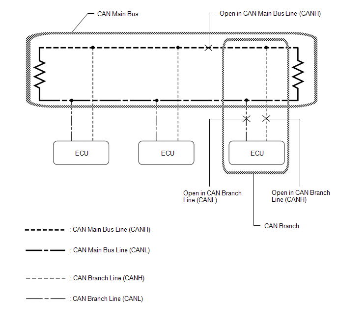
HINT:
- This waveform is measured between terminals CANH and GND, and terminals CANL and GND of the central gateway ECU (network gateway ECU). (Use this as a reference for diagnosis of CAN communication lines.)
- When malfunctions in multiple ECUs are suspected based on the CAN bus
check and DTCs checked using the Techstream, check the resistance of the
CAN bus using an ohmmeter first. If no problems are found, check the following
waveforms.
Click here
- If a waveform is not similar to one of the following 3 patterns (Group 1), then an open in a CAN main bus line, an open in a CAN branch line, or a short between a CAN line (CANH or CANL) and ground is suspected (Group 2).
- Wiggle the connector and wire harness to check if the waveform changes.
(a) CAN bus waveforms (Group 1)
(1) Normal waveform
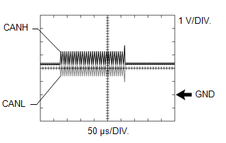
(2) Open in both of the lines (CANH and CANL) of a CAN branch
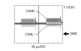
HINT:
- Waveforms (waveforms shown using dotted lines) are not present from an ECU or sensor connected to a CAN branch with an open circuit in both lines. (Waveforms from other ECUs or sensors are normal.)
- Because this waveform is similar to a normal waveform, instead of using the waveform, the malfunctioning part can be narrowed down by performing a CAN bus check.
(3) Short between the CAN bus lines (CANH and CANL)
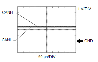
HINT:
- Waveforms disappear.
- If the malfunction is in an ECU, disconnecting the ECU will change the waveform. If the waveform does not change, a malfunction in the wire harness is suspected.
(b) CAN bus waveforms (reference) (Group 2)
NOTICE:
The following CAN bus waveforms can be used only as reference. The actual measured waveform may differ significantly depending on the location of the open or short circuit.
(1) Open in a CAN branch line (CANH)
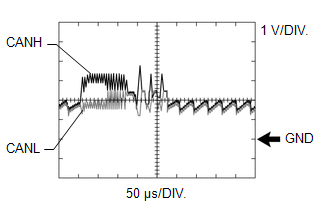
HINT:
- An abnormal waveform is output from an ECU with an open in one of its CAN branch lines. Because this abnormal output interferes with the signals from other ECUs, the output of other ECUs will also appear abnormal.
- Narrow down the malfunctioning part by checking DTCs or performing a CAN bus check, or by checking waveform changes when ECUs or sensors are disconnected. The waveform will change to one for an open in both sides of a CAN branch when the ECU or sensor with an open CAN branch line is disconnected.
(2) Open in a CAN branch line (CANL)
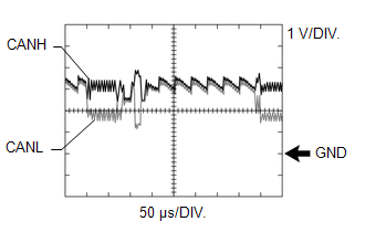
HINT:
- An abnormal waveform is output from an ECU with an open in one of its CAN branch lines. Because this abnormal output interferes with the signals from other ECUs, the output of other ECUs will also appear abnormal.
- Narrow down the malfunctioning part by checking DTCs or performing a CAN bus check, or by checking waveform changes when ECUs or sensors are disconnected. The waveform will change to one for an open in both sides of a CAN branch when the ECU or sensor with an open CAN branch line is disconnected.
(3) Open in a CAN main bus line (CANH)
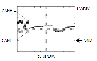
HINT:
- Waveforms of ECUs or sensors that are closer to the central gateway ECU (network gateway ECU) than the open part are almost normal.
- Waveforms of ECUs or sensors that are on the opposite side of the central gateway ECU (network gateway ECU) from the open part are abnormal.
- An open in a CAN main bus line can be confirmed by measuring the resistance between the CANH and CANL terminals of any CAN branch.
(4) Short between a CAN bus line (CANH) and ground
HINT:
- Narrow down the shorted part by checking for waveform changes when disconnecting connectors from the CAN junction connectors or when disconnecting ECUs or sensors.
- A short to ground in the CANH line can be confirmed by measuring the resistance between CANH and ground using an ohmmeter.
(5) Short between a CAN bus line (CANL) and ground
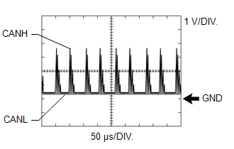
HINT:
- Narrow down the shorted part by checking for waveform changes when disconnecting connectors from the CAN junction connectors or when disconnecting ECUs or sensors.
- A short to ground in the CANL line can be confirmed by measuring the resistance between CANL and ground using an ohmmeter.
DATA SENDING/RECEIVING TABLE
(a) Data sending/receiving table
HINT:
If Data List items related to sent/received data are not displayed properly, the part for which communication is interrupted can be determined using the table below.
|
Data Content |
Data Detected and Sent by |
Data Received by |
Relevant Data List Item |
|||
|---|---|---|---|---|---|---|
|
Can be Checked in the Data List |
Cannot be Checked in the Data List |
Selected System |
Data List Items |
Link |
||
|
Accelerator position |
ECM |
Brake actuator assembly |
|
Engine and ECT |
Accelerator Position (w/ Canister Pump Module) |
|
|
Accelerator Position (w/o Canister Pump Module) |
|
|||||
|
ABS/VSC/TRAC/EPB |
Accelerator Opening Angle % |
|
||||
|
Engine speed |
ECM |
|
|
Engine and ECT |
Engine Speed (w/ Canister Pump Module) |
|
|
Engine Speed (w/o Canister Pump Module) |
|
|||||
|
ABS/VSC/TRAC/EPB |
Engine Revolution |
|
||||
|
EMPS |
Engine Revolution |
|
||||
|
Engine coolant temperature |
ECM |
|
- |
Engine and ECT |
Coolant Temperature (w/ Canister Pump Module) |
|
|
Coolant Temperature (w/o Canister Pump Module) |
|
|||||
|
Combination Meter |
Coolant Temperature |
|
||||
|
Air Conditioner |
Engine Coolant Temp (w/ Top-mounted Air Conditioner Pressure Sensor) |
|
||||
|
Engine Coolant Temp (w/ Side-mounted Air Conditioner Pressure Sensor) |
|
|||||
|
Vehicle speed |
Brake actuator assembly |
|
|
ABS/VSC/TRAC/EPB |
Vehicle Speed |
|
|
EMPS |
Meter Vehicle Velocity |
|
||||
|
Engine and ECT |
Vehicle Speed (w/ Canister Pump Module) |
|
||||
|
Vehicle Speed (w/o Canister Pump Module) |
|
|||||
|
Combination Meter |
Vehicle Speed Meter |
|
||||
|
Navigation System |
Vehicle Speed |
|
||||
|
Radar Cruise2 |
Vehicle Spd-Brake ECU |
|
||||
|
Occupant Detection |
VSC Vehicle Speed |
|
||||
|
Vehicle speed |
Combination meter assembly*3 |
- |
|
Combination Meter |
Vehicle Speed Meter |
|
|
Wheel speed |
Brake actuator assembly |
|
|
ABS/VSC/TRAC/EPB |
|
|
|
HL Auto Leveling |
|
|
||||
|
EMPS |
|
|
||||
|
Shift position |
ECM |
|
|
Engine and ECT |
Neutral Position SW (w/ Canister Pump Module) |
|
|
Neutral Position SW (w/o Canister Pump Module) |
|
|||||
|
Power Source Control |
Shift P Signal |
|
||||
|
Navigation System |
Reverse Signal |
|
||||
|
Blind Spot Monitor Master |
Reverse (Only for AT/CVT) |
|
||||
|
Ambient temperature |
Air conditioning amplifier assembly |
Combination meter assembly |
|
Air Conditioner |
Ambient Temp Sensor (w/ Top-mounted Air Conditioner Pressure Sensor) |
|
|
Ambient Temp Sensor (w/ Side-mounted Air Conditioner Pressure Sensor) |
|
|||||
|
Combination Meter |
Ambient Temperature |
|
||||
|
Driver door courtesy switch |
Main body ECU (multiplex network body ECU) |
- |
|
Main Body |
FL Door Courtesy SW |
|
|
Steering angle |
Steering sensor |
|
|
Blind Spot Monitor Master |
Steering Angle |
|
|
EMPS |
Steering Angle Velocity |
|
||||
|
ABS/VSC/TRAC/EPB |
Steering Angle Sensor |
|
||||
|
Radar Cruise2 |
Steering Angle |
|
||||
|
Yaw rate |
Airbag sensor assembly |
|
|
ABS/VSC/TRAC/EPB |
|
|
|
Radar Cruise2 |
Yaw Rate Sensor |
|
||||
|
Acceleration |
Airbag sensor assembly |
|
|
ABS/VSC/TRAC/EPB |
|
|
|
Occupant Detection |
|
|
||||
|
Ignition switch condition |
Main body ECU (multiplex network body ECU) |
Headlight ECU sub-assembly LH |
Certification ECU (smart key ECU assembly) |
Main Body |
IG SW |
|
|
HL Auto Leveling |
+B |
|
||||
|
Stop light switch signal |
Brake actuator assembly |
Certification ECU (smart key ECU assembly) |
|
ABS/VSC/TRAC/EPB |
Stop Light SW |
|
|
Power Source Control |
Stop Light Switch1 |
|
||||
|
Headlight switch signal (high beam) |
Main body ECU (multiplex network body ECU) |
Headlight ECU sub-assembly LH |
|
Main Body |
Head Light SW (Head) |
|
|
HL Auto Leveling |
HeadLight High Beam State |
|
||||
|
Side turn signal |
Combination meter assembly*2 |
|
|
Combination Meter |
|
|
|
Blind Spot Monitor Master |
Turn Switch State |
|
||||
|
LKA/LDA |
|
|
||||
|
Taillight signal |
Main body ECU (multiplex network body ECU) |
Headlight ECU sub-assembly LH |
|
Main Body |
Head Light SW (Tail) |
|
|
HL Auto Leveling |
Clearance Light State |
|
||||
|
ECM power source voltage*1 |
ECM |
- |
- |
Engine and ECT |
BATT Voltage |
|
|
Combination meter assembly power source voltage*1 |
Combination meter assembly |
- |
- |
Combination Meter |
+B Voltage Value |
|
|
Power steering ECU assembly power source voltage*1 |
Power steering ECU assembly |
- |
- |
EMPS |
IG Power Supply |
|
|
Headlight ECU sub-assembly LH power source voltage*1 |
Headlight ECU sub-assembly LH |
- |
- |
HL Auto Leveling |
+B Voltage Value |
|
|
Driver door touch sensor*1 |
Certification ECU (smart key ECU assembly) |
- |
- |
Smart Key |
D-Door Touch Sensor |
|
|
Blind spot monitor main switch condition*1 |
Blind spot monitor sensor LH |
- |
- |
Blind Spot Monitor Master |
Main Switch |
|
|
Solar sensor*1 |
Air conditioning amplifier assembly |
- |
- |
Air Conditioner |
Solar Sensor (D Side) (w/ Top-mounted Air Conditioner Pressure Sensor) |
|
|
Solar Sensor (D Side) (w/ Side-mounted Air Conditioner Pressure Sensor) |
|
|||||
|
Radio and display receiver assembly power source voltage*1 |
Radio and display receiver assembly |
- |
- |
Navigation System |
Battery Voltage |
|
- *1: Whether the ECU that sends data is functioning or not can be judged by using the Techstream to check items such as switches or sensors that send signals to the ECU via direct lines.
- *2: Although the received contents cannot be checked in the Data List, whether or not the data is received normally can be checked by observing the combination meter assembly.
- *3: The combination meter assembly receives a vehicle speed signal from the brake actuator assembly and sends the signal to other ECUs.
 Terminals Of Ecu
TERMINALS OF ECU
NOTICE:
After turning the ignition switch off, waiting time may be required
before disconnecting the cable from the negative (-) battery terminal. Therefore,
make su ...
 Dtc Combination Table
DTC COMBINATION TABLE
HOW TO INTERPRET COMMUNICATION DTCS (DTCS THAT START WITH U)
(a) If a CAN communication error cannot be reproduced, determine the suspected
malfunctioning part using the DTCs ...
Other materials:
Toyota CH-R Service Manual > Audio And Visual System(for Radio Receiver Type): Terminals Of Ecu
TERMINALS OF ECU
Terminal No. (Symbol)
Wiring Color
Terminal Description
Condition
Specified Condition
F47-4 (MACC) - F48-7 (GND1)
B - LA
Microphone power supply
Ignition switch off
...
Toyota CH-R Service Manual > Seat Belt Warning System(w/o Occupant Classification System): Problem Symptoms Table
PROBLEM SYMPTOMS TABLE
HINT:
Use the table below to help determine the cause of problem symptoms.
If multiple suspected areas are listed, the potential causes of the symptoms
are listed in order of probability in the "Suspected Area" column of the
table. Check each sy ...
Toyota C-HR (AX20) 2023-2026 Owner's Manual
Toyota CH-R Owners Manual
- For safety and security
- Instrument cluster
- Operation of each component
- Driving
- Interior features
- Maintenance and care
- When trouble arises
- Vehicle specifications
- For owners
Toyota CH-R Service Manual
- Introduction
- Maintenance
- Audio / Video
- Cellular Communication
- Navigation / Multi Info Display
- Park Assist / Monitoring
- Brake (front)
- Brake (rear)
- Brake Control / Dynamic Control Systems
- Brake System (other)
- Parking Brake
- Axle And Differential
- Drive Shaft / Propeller Shaft
- K114 Cvt
- 3zr-fae Battery / Charging
- Networking
- Power Distribution
- Power Assist Systems
- Steering Column
- Steering Gear / Linkage
- Alignment / Handling Diagnosis
- Front Suspension
- Rear Suspension
- Tire / Wheel
- Tire Pressure Monitoring
- Door / Hatch
- Exterior Panels / Trim
- Horn
- Lighting (ext)
- Mirror (ext)
- Window / Glass
- Wiper / Washer
- Door Lock
- Heating / Air Conditioning
- Interior Panels / Trim
- Lighting (int)
- Meter / Gauge / Display
- Mirror (int)
- Power Outlets (int)
- Pre-collision
- Seat
- Seat Belt
- Supplemental Restraint Systems
- Theft Deterrent / Keyless Entry

0.1298