Toyota CH-R Service Manual: Terminals Of Ecu
TERMINALS OF ECU
NOTICE:
- After turning the ignition switch off, waiting time may be required
before disconnecting the cable from the negative (-) battery terminal. Therefore,
make sure to read the disconnecting the cable from the negative (-) battery
terminal notices before proceeding with work.
Click here
.gif)
- Before measuring the resistance of the CAN bus, turn the ignition switch off and leave the vehicle for 1 minute or more without operating the key or any switches, or opening or closing the doors. After that, disconnect the cable from the negative (-) battery terminal and leave the vehicle for 1 minute or more before measuring the resistance.
- This section describes the standard values for all CAN related components.
HINT:
- The systems (ECUs and sensors) that use CAN communication vary depending
on the vehicle and optional equipment. Check which systems (ECUs and sensors)
are installed to the vehicle.
Click here
- Operating the ignition switch, any other switches or a door triggers related ECU and sensor communication on the CAN. This communication will cause the resistance value to change.
- Even after DTCs are cleared, if a DTC is stored again after driving the vehicle for a while, the malfunction may be occurring due to vibration of the vehicle. In such a case, wiggling the ECUs or wire harness while performing the inspection below may help determine the cause of the malfunction.
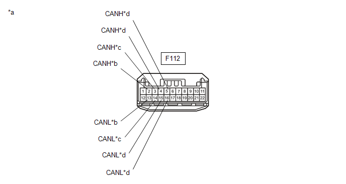
NO. 1 CAN JUNCTION CONNECTOR (w/o Blind Spot Monitor System)
(a) Check the No. 1 CAN junction connector.
(1) Connection diagram
|
*a |
Front view of wire harness connector (to No. 1 CAN Junction Connector) |
*b |
to Forward Recognition Camera (w/ Toyota Safety Sense P) |
|
*c |
to Millimeter Wave Radar Sensor Assembly (w/ Toyota Safety Sense P) |
*d |
to Central Gateway ECU (Network Gateway ECU) |
(2) Check the connection diagram of the components which are connected to the No. 1 CAN junction connector.
|
Terminal No. (Symbol) |
Wiring Color |
Connected to |
|---|---|---|
|
F112-2 (CANH) |
R |
Forward recognition camera*1 (for Bus 1) |
|
F112-13 (CANL) |
GR |
|
|
F112-3 (CANH) |
G |
Millimeter wave radar sensor assembly*1 (for Bus 1) |
|
F112-14 (CANL) |
GR |
|
|
F112-4 (CANH) |
B |
Central gateway ECU (network gateway ECU) (for Bus 1) |
|
F112-15 (CANL) |
GR |
|
|
F112-5 (CANH) |
P |
Central gateway ECU (network gateway ECU) (for Bus 1) |
|
F112-16 (CANL) |
GR |
- *1: w/ Toyota Safety Sense P
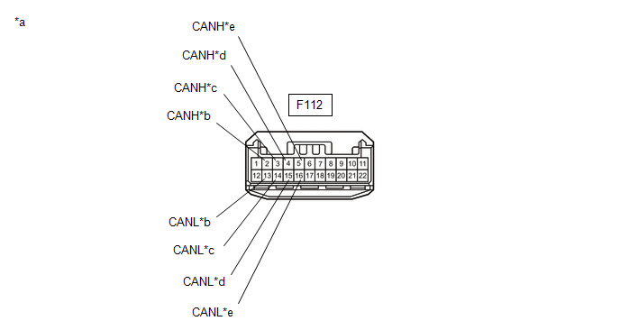
NO. 1 CAN JUNCTION CONNECTOR (w/ Blind Spot Monitor System)
(a) Check the No. 1 CAN junction connector.
(1) Connection diagram
|
*a |
Front view of wire harness connector (to No. 1 CAN Junction Connector) |
*b |
to Forward Recognition Camera (w/ Toyota Safety Sense P) |
|
*c |
to Millimeter Wave Radar Sensor Assembly (w/ Toyota Safety Sense P) |
*d |
to No. 6 CAN Junction Connector |
|
*e |
to Central Gateway ECU (Network Gateway ECU) |
- |
- |
(2) Check the connection diagram of the components which are connected to the No. 1 CAN junction connector.
|
Terminal No. (Symbol) |
Wiring Color |
Connected to |
|---|---|---|
|
F112-2 (CANH) |
R |
Forward recognition camera*1 (for Bus 1) |
|
F112-13 (CANL) |
GR |
|
|
F112-3 (CANH) |
G |
Millimeter wave radar sensor assembly*1 (for Bus 1) |
|
F112-14 (CANL) |
GR |
|
|
F112-4 (CANH) |
B |
No. 6 CAN junction connector (for Bus 1) |
|
F112-15 (CANL) |
GR |
|
|
F112-5 (CANH) |
P |
Central gateway ECU (network gateway ECU) (for Bus 1) |
|
F112-16 (CANL) |
GR |
- *1: w/ Toyota Safety Sense P
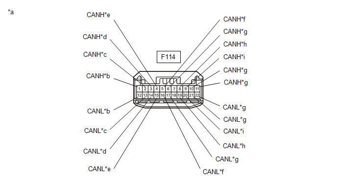
NO. 3 CAN JUNCTION CONNECTOR
(a) Check the No. 3 CAN junction connector.
(1) Connection diagram
|
*a |
Front view of wire harness connector (to No. 3 CAN Junction Connector) |
*b |
to Combination Meter Assembly |
|
*c |
to Main Body ECU (Multiplex Network Body ECU) |
*d |
to Headlight ECU Sub-assembly LH (for LED Headlight) |
|
*e |
to Air Conditioning Amplifier Assembly |
*f |
to Certification ECU (Smart Key ECU Assembly) (w/ Smart Key System) |
|
*g |
to Central Gateway ECU (Network Gateway ECU) |
*h |
to DCM (Telematics Transceiver) (w/ Telematics Transceiver) |
|
*i |
to Radio and Display Receiver Assembly (for Radio and Display Type) |
- |
- |
(2) Check the connection diagram of the components which are connected to the No. 3 CAN junction connector.
|
Terminal No. (Symbol) |
Wiring Color |
Connected to |
|---|---|---|
|
F114-1 (CANH) |
V |
Combination meter assembly (for Bus 5) |
|
F114-12 (CANL) |
SB |
|
|
F114-2 (CANH) |
G |
Main body ECU (multiplex network body ECU) (for Bus 5) |
|
F114-13 (CANL) |
SB |
|
|
F114-3 (CANH) |
L |
Headlight ECU Sub-assembly LH*1 (for Bus 5) |
|
F114-14 (CANL) |
SB |
|
|
F114-4 (CANH) |
P |
Air conditioning amplifier assembly (for Bus 5) |
|
F114-15 (CANL) |
SB |
|
|
F114-5 (CANH) |
R |
Certification ECU (smart key ECU assembly)*2 (for Bus 5) |
|
F114-16 (CANL) |
SB |
|
|
F114-6 (CANH) |
B |
Central gateway ECU (network gateway ECU) (for Bus 5) |
|
F114-17 (CANL) |
SB |
|
|
F114-8 (CANH) |
GR |
DCM (Telematics transceiver)*3 (for Bus 3) |
|
F114-19 (CANL) |
LG |
|
|
F114-9 (CANH) |
B |
Radio and display receiver assembly*4 (for Bus 3) |
|
F114-20 (CANL) |
LG |
|
|
F114-10 (CANH) |
G |
Central gateway ECU (network gateway ECU) (for Bus 3) |
|
F114-21 (CANL) |
LG |
|
|
F114-11 (CANH) |
V |
Central gateway ECU (network gateway ECU) (for Bus 3) |
|
F114-22 (CANL) |
LG |
- *1: for LED Headlight
- *2: w/ Smart Key System
- *3: w/ Telematics Transceiver
- *4: for Radio and Display Type
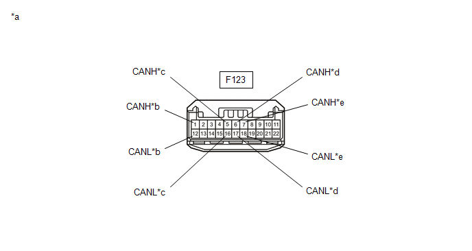
NO. 4 CAN JUNCTION CONNECTOR
(a) Check the No. 4 CAN junction connector.
(1) Connection diagram
|
*a |
Front view of wire harness connector (to No. 4 CAN Junction Connector) |
*b |
to Airbag Sensor Assembly |
|
*c |
to Steering Sensor |
*d |
to Power Steering ECU Assembly |
|
*e |
to No. 5 CAN Junction Connector |
- |
- |
(2) Check the connection diagram of the components which are connected to the No. 4 CAN junction connector.
|
Terminal No. (Symbol) |
Wiring Color |
Connected to |
|---|---|---|
|
F123-1 (CANH) |
B |
Airbag sensor assembly (for Bus 4) |
|
F123-12 (CANL) |
W |
|
|
F123-5 (CANH) |
BE |
Steering sensor (for Bus 4) |
|
F123-16 (CANL) |
W |
|
|
F123-6 (CANH) |
P |
Power steering ECU assembly (for Bus 4) |
|
F123-17 (CANL) |
W |
|
|
F123-7 (CANH) |
GR |
No. 5 CAN junction connector (for Bus 4) |
|
F123-18 (CANL) |
W |
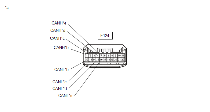
NO. 5 CAN JUNCTION CONNECTOR
(a) Check the No. 5 CAN junction connector.
(1) Connection diagram
|
*a |
Front view of wire harness connector (to No. 5 CAN Junction Connector) |
*b |
to No. 4 CAN Junction Connector |
|
*c |
to Central Gateway ECU (Network Gateway ECU) |
*d |
to Occupant Detection ECU (w/ Occupant Detection ECU) |
|
*e |
to Brake Actuator Assembly |
- |
- |
(2) Check the connection diagram of the components which are connected to the No. 5 CAN junction connector.
|
Terminal No. (Symbol) |
Wiring Color |
Connected to |
|---|---|---|
|
F124-1 (CANH) |
GR |
No. 4 CAN junction connector (for Bus 4) |
|
F124-12 (CANL) |
W |
|
|
F124-2 (CANH) |
B |
Central gateway ECU (network gateway ECU) (for Bus 4) |
|
F124-13 (CANL) |
W |
|
|
F124-4 (CANH) |
SB |
Occupant detection ECU*1 (for Bus 4) |
|
F124-15 (CANL) |
W |
|
|
F124-5 (CANH) |
LG |
Brake actuator assembly (for Bus 4) |
|
F124-16 (CANL) |
W |
- *1: w/ Occupant Detection ECU
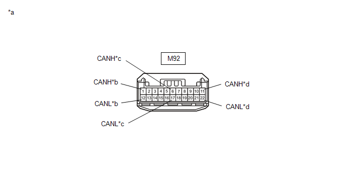
NO. 6 CAN JUNCTION CONNECTOR (w/ Blind Spot Monitor System)
(a) Check the No. 6 CAN junction connector.
(1) Connection diagram
|
*a |
Front view of wire harness connector (to No. 6 CAN Junction Connector) |
*b |
to Central Gateway ECU (Network Gateway ECU) |
|
*c |
to Blind Spot Monitor Sensor LH |
*d |
to No. 1 CAN Junction Connector |
(2) Check the connection diagram of the components which are connected to the No. 6 CAN junction connector.
|
Terminal No. (Symbol) |
Wiring Color |
Connected to |
|---|---|---|
|
M92-1 (CANH) |
R |
Central gateway ECU (network gateway ECU) (for Bus 1) |
|
M92-12 (CANL) |
GR |
|
|
M92-6 (CANH) |
G |
Blind spot monitor sensor LH (for Bus 1) |
|
M92-17 (CANL) |
GR |
|
|
M92-11 (CANH) |
B |
No. 1 CAN junction connector (for Bus 1) |
|
M92-22 (CANL) |
GR |
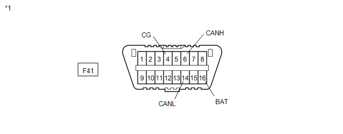
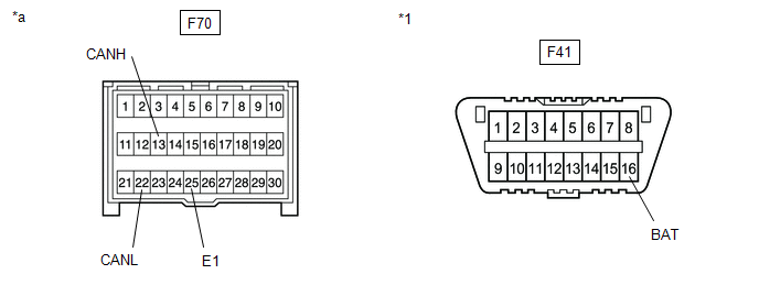
DLC3
(a) Disconnect the cable from the negative (-) battery terminal.
(b) Measure the resistance according to the value(s) in the table below.
|
*1 |
DLC3 |
- |
- |
Standard Resistance:
|
Terminal No. (Symbol) |
Wiring Color |
Terminal Description |
Condition |
Specified Condition |
|---|---|---|---|---|
|
F41-6 (CANH) - F41-14 (CANL) |
R - W |
HIGH-level CAN bus line - LOW-level CAN bus line |
Cable disconnected from negative (-) battery terminal |
54 to 69 Ω |
|
F41-6 (CANH) - F41-4 (CG) |
R - W-B |
HIGH-level CAN bus line - Ground |
Cable disconnected from negative (-) battery terminal |
200 Ω or higher |
|
F41-14 (CANL) - F41-4 (CG) |
W - W-B |
LOW-level CAN bus line - Ground |
Cable disconnected from negative (-) battery terminal |
200 Ω or higher |
|
F41-6 (CANH) - F41-16 (BAT) |
R - R |
HIGH-level CAN bus line - Battery positive (+) |
Cable disconnected from negative (-) battery terminal |
6 kΩ or higher |
|
F41-14 (CANL) - F41-16 (BAT) |
W - R |
LOW-level CAN bus line - Battery positive (+) |
Cable disconnected from negative (-) battery terminal |
6 kΩ or higher |
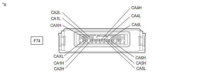
CENTRAL GATEWAY ECU (NETWORK GATEWAY ECU)
|
*a |
Component without harness connected (Central Gateway ECU (Network Gateway ECU)) |
- |
- |
(a) Disconnect the cable from the negative (-) battery terminal.
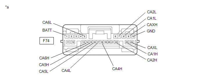
(b) Disconnect the F74 central gateway ECU (network gateway ECU) connector.
(c) Measure the resistance according to the value(s) in the table below.
|
*a |
Front view of wire harness connector (to Central Gateway ECU (Network Gateway ECU)) |
- |
- |
Standard Resistance:
Diagnosis Bus Branch Lines (DLC3 - Central gateway ECU (network gateway ECU))|
Terminal No. (Symbol) |
Wiring Color |
Terminal Description |
Condition |
Specified Condition |
|---|---|---|---|---|
|
F74-14 (CA6H) - F74-5 (CA6L) |
R - W |
HIGH-level CAN bus line - LOW-level CAN bus line |
Cable disconnected from negative (-) battery terminal |
1 MΩ or higher |
|
F74-14 (CA6H) - F74-10 (GND) |
R - W-B |
HIGH-level CAN bus line - Ground |
Cable disconnected from negative (-) battery terminal |
200 Ω or higher |
|
F74-5 (CA6L) - F74-10 (GND) |
W - W-B |
LOW-level CAN bus line - Ground |
Cable disconnected from negative (-) battery terminal |
200 Ω or higher |
|
F74-14 (CA6H) - F74-1 (BATT) |
R - Y |
HIGH-level CAN bus line - Battery positive (+) |
Cable disconnected from negative (-) battery terminal |
6 kΩ or higher |
|
F74-5 (CA6L) - F74-1 (BATT) |
W - Y |
LOW-level CAN bus line - Battery positive (+) |
Cable disconnected from negative (-) battery terminal |
6 kΩ or higher |
|
Terminal No. (Symbol) |
Wiring Color |
Terminal Description |
Condition |
Specified Condition |
|---|---|---|---|---|
|
F74-23 (CA1H) - F74-9 (CAXH) |
R - P |
HIGH-level CAN bus line - HIGH-level CAN bus line |
Cable disconnected from negative (-) battery terminal |
Below 1 Ω |
|
F74-8 (CA1L) - F74-24 (CAXL) |
GR - GR |
LOW-level CAN bus line - LOW-level CAN bus line |
Cable disconnected from negative (-) battery terminal |
Below 1 Ω |
|
F74-23 (CA1H) - F74-10 (GND) |
R - W-B |
HIGH-level CAN bus line - Ground |
Cable disconnected from negative (-) battery terminal |
200 Ω or higher |
|
F74-8 (CA1L) - F74-10 (GND) |
GR - W-B |
LOW-level CAN bus line - Ground |
Cable disconnected from negative (-) battery terminal |
200 Ω or higher |
|
F74-23 (CA1H) - F74-1 (BATT) |
R - Y |
HIGH-level CAN bus line - Battery positive (+) |
Cable disconnected from negative (-) battery terminal |
6 kΩ or higher |
|
F74-8 (CA1L) - F74-1 (BATT) |
GR - Y |
LOW-level CAN bus line - Battery positive (+) |
Cable disconnected from negative (-) battery terminal |
6 kΩ or higher |
|
Terminal No. (Symbol) |
Wiring Color |
Terminal Description |
Condition |
Specified Condition |
|---|---|---|---|---|
|
F74-18 (CA4H) - F74-17 (CA4L) |
R - P |
HIGH-level CAN bus line - LOW-level CAN bus line |
Cable disconnected from negative (-) battery terminal |
108 to 132 Ω |
|
F74-18 (CA4H) - F74-10 (GND) |
R - W-B |
HIGH-level CAN bus line - Ground |
Cable disconnected from negative (-) battery terminal |
200 Ω or higher |
|
F74-17 (CA4L) - F74-10 (GND) |
P - W-B |
LOW-level CAN bus line - Ground |
Cable disconnected from negative (-) battery terminal |
200 Ω or higher |
|
F74-18 (CA4H) - F74-1 (BATT) |
R - Y |
HIGH-level CAN bus line - Battery positive (+) |
Cable disconnected from negative (-) battery terminal |
6 kΩ or higher |
|
F74-17 (CA4L) - F74-1 (BATT) |
P - Y |
LOW-level CAN bus line - Battery positive (+) |
Cable disconnected from negative (-) battery terminal |
6 kΩ or higher |
|
Terminal No. (Symbol) |
Wiring Color |
Terminal Description |
Condition |
Specified Condition |
|---|---|---|---|---|
|
F74-22 (CA2H) - F74-7 (CA2L) |
B - W |
HIGH-level CAN bus line - LOW-level CAN bus line |
Cable disconnected from negative (-) battery terminal |
108 to 132 Ω |
|
F74-22 (CA2H) - F74-10 (GND) |
B - W-B |
HIGH-level CAN bus line - Ground |
Cable disconnected from negative (-) battery terminal |
200 Ω or higher |
|
F74-7 (CA2L) - F74-10 (GND) |
W - W-B |
LOW-level CAN bus line - Ground |
Cable disconnected from negative (-) battery terminal |
200 Ω or higher |
|
F74-22 (CA2H) - F74-1 (BATT) |
B - Y |
HIGH-level CAN bus line - Battery positive (+) |
Cable disconnected from negative (-) battery terminal |
6 kΩ or higher |
|
F74-7 (CA2L) - F74-1 (BATT) |
W - Y |
LOW-level CAN bus line - Battery positive (+) |
Cable disconnected from negative (-) battery terminal |
6 kΩ or higher |
|
Terminal No. (Symbol) |
Wiring Color |
Terminal Description |
Condition |
Specified Condition |
|---|---|---|---|---|
|
F74-15 (CA5H) - F74-16 (CA5L) |
B - SB |
HIGH-level CAN bus line - LOW-level CAN bus line |
Cable disconnected from negative (-) battery terminal |
108 to 132 Ω |
|
F74-15 (CA5H) - F74-10 (GND) |
B - W-B |
HIGH-level CAN bus line - Ground |
Cable disconnected from negative (-) battery terminal |
200 Ω or higher |
|
F74-16 (CA5L) - F74-10 (GND) |
SB - W-B |
LOW-level CAN bus line - Ground |
Cable disconnected from negative (-) battery terminal |
200 Ω or higher |
|
F74-15 (CA5H) - F74-1 (BATT) |
B - Y |
HIGH-level CAN bus line - Battery positive (+) |
Cable disconnected from negative (-) battery terminal |
6 kΩ or higher |
|
F74-16 (CA5L) - F74-1 (BATT) |
SB - Y |
LOW-level CAN bus line - Battery positive (+) |
Cable disconnected from negative (-) battery terminal |
6 kΩ or higher |
STEERING SENSOR
|
*a |
Component without harness connected (Steering Sensor) |
- |
- |
(a) Disconnect the cable from the negative (-) battery terminal.
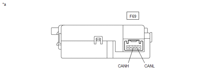
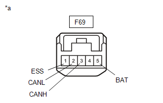
(b) Disconnect the F69 steering sensor connector.
(c) Measure the resistance according to the value(s) in the table below.
|
*a |
Front view of wire harness connector (to Steering Sensor) |
Standard Resistance:
|
Terminal No. (Symbol) |
Wiring Color |
Terminal Description |
Condition |
Specified Condition |
|---|---|---|---|---|
|
F69-3 (CANH) - F69-2 (CANL) |
BE - W |
HIGH-level CAN bus line - LOW-level CAN bus line |
Cable disconnected from negative (-) battery terminal |
54 to 69 Ω |
|
F69-3 (CANH) - F69-1 (ESS) |
BE - W-B |
HIGH-level CAN bus line - Ground |
Cable disconnected from negative (-) battery terminal |
200 Ω or higher |
|
F69-2 (CANL) - F69-1 (ESS) |
W - W-B |
LOW-level CAN bus line - Ground |
Cable disconnected from negative (-) battery terminal |
200 Ω or higher |
|
F69-3 (CANH) - F69-5 (BAT) |
BE - P |
HIGH-level CAN bus line - Battery positive (+) |
Cable disconnected from negative (-) battery terminal |
6 kΩ or higher |
|
F69-2 (CANL) - F69-5 (BAT) |
W - P |
LOW-level CAN bus line - Battery positive (+) |
Cable disconnected from negative (-) battery terminal |
6 kΩ or higher |
ECM
Refer to Terminals of ECU.
- w/ Canister Pump Module: Click here
- w/o Canister Pump Module: Click here
(a) Disconnect the cable from the negative (-) battery terminal.
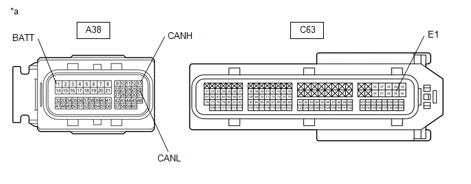
(b) Disconnect the A38 and C63 ECM connectors.
(c) Measure the resistance according to the value(s) in the table below.
|
*a |
Front view of wire harness connector (to ECM) |
- |
- |
Standard Resistance:
|
Terminal No. (Symbol) |
Wiring Color |
Terminal Description |
Condition |
Specified Condition |
|---|---|---|---|---|
|
A38-13 (CANH) - A38-26 (CANL) |
R - P |
HIGH-level CAN bus line - LOW-level CAN bus line |
Cable disconnected from negative (-) battery terminal |
108 to 132 Ω |
|
A38-13 (CANH) - C63-59 (E1) |
R - W-B |
HIGH-level CAN bus line - Ground |
Cable disconnected from negative (-) battery terminal |
200 Ω or higher |
|
A38-26 (CANL) - C63-59 (E1) |
P - W-B |
LOW-level CAN bus line - Ground |
Cable disconnected from negative (-) battery terminal |
200 Ω or higher |
|
A38-13 (CANH) - A38-1 (BATT) |
R - R |
HIGH-level CAN bus line - Battery positive (+) |
Cable disconnected from negative (-) battery terminal |
6 kΩ or higher |
|
A38-26 (CANL) - A38-1 (BATT) |
P - R |
LOW-level CAN bus line - Battery positive (+) |
Cable disconnected from negative (-) battery terminal |
6 kΩ or higher |
COMBINATION METER ASSEMBLY
Refer to Terminals of ECU.
Click here
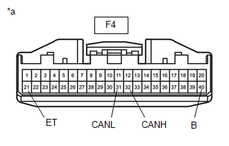
(a) Disconnect the cable from the negative (-) battery terminal.
(b) Disconnect the F4 combination meter assembly connector.
(c) Measure the resistance according to the value(s) in the table below.
|
*a |
Front view of wire harness connector (to Combination Meter Assembly) |
Standard Resistance:
|
Terminal No. (Symbol) |
Wiring Color |
Terminal Description |
Condition |
Specified Condition |
|---|---|---|---|---|
|
F4-32 (CANH) - F4-31 (CANL) |
V - SB |
HIGH-level CAN bus line - LOW-level CAN bus line |
Cable disconnected from negative (-) battery terminal |
108 to 132 Ω |
|
F4-32 (CANH) - F4-21 (ET) |
V - W-B |
HIGH-level CAN bus line - Ground |
Cable disconnected from negative (-) battery terminal |
200 Ω or higher |
|
F4-31 (CANL) - F4-21 (ET) |
SB - W-B |
LOW-level CAN bus line - Ground |
Cable disconnected from negative (-) battery terminal |
200 Ω or higher |
|
F4-32 (CANH) - F4-40 (B) |
V - SB |
HIGH-level CAN bus line - Battery positive (+) |
Cable disconnected from negative (-) battery terminal |
6 kΩ or higher |
|
F4-31 (CANL) - F4-40 (B) |
SB - SB |
LOW-level CAN bus line - Battery positive (+) |
Cable disconnected from negative (-) battery terminal |
6 kΩ or higher |
BRAKE ACTUATOR ASSEMBLY
Refer to Terminals of ECU.
Click here
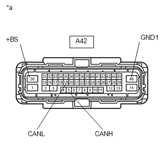
(a) Disconnect the cable from the negative (-) battery terminal.
(b) Disconnect the A42 brake actuator assembly connector.
(c) Measure the resistance according to the value(s) in the table below.
Standard Resistance:
|
Terminal No. (Symbol) |
Wiring Color |
Terminal Description |
Condition |
Specified Condition |
|---|---|---|---|---|
|
A42-5 (CANH) - A42-19 (CANL) |
LG - W |
HIGH-level CAN bus line - LOW-level CAN bus line |
Cable disconnected from negative (-) battery terminal |
54 to 69 Ω |
|
A42-5 (CANH) - A42-46 (GND1) |
LG - W-B |
HIGH-level CAN bus line - Ground |
Cable disconnected from negative (-) battery terminal |
200 Ω or higher |
|
A42-19 (CANL) - A42-46 (GND1) |
W - W-B |
LOW-level CAN bus line - Ground |
Cable disconnected from negative (-) battery terminal |
200 Ω or higher |
|
A42-5 (CANH) - A42-30 (+BS) |
LG - W |
HIGH-level CAN bus line - Battery positive (+) |
Cable disconnected from negative (-) battery terminal |
6 kΩ or higher |
|
A42-19 (CANL) - A42-30 (+BS) |
W - W |
LOW-level CAN bus line - Battery positive (+) |
Cable disconnected from negative (-) battery terminal |
6 kΩ or higher |
|
*a |
Front view of wire harness connector (to Brake Actuator Assembly) |
MAIN BODY ECU (MULTIPLEX NETWORK BODY ECU)
Refer to Terminals of ECU.
Click here
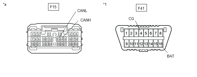
(a) Disconnect the cable from the negative (-) battery terminal.
(b) Disconnect the F15 main body ECU (multiplex network body ECU) connector.
(c) Measure the resistance according to the value(s) in the table below.
|
*1 |
DLC3 |
- |
- |
|
*a |
Front view of wire harness connector (to Main Body ECU (Multiplex Network Body ECU)) |
- |
- |
Standard Resistance:
|
Terminal No. (Symbol) |
Wiring Color |
Terminal Description |
Condition |
Specified Condition |
|---|---|---|---|---|
|
F15-14 (CANH) - F15-13 (CANL) |
G - SB |
HIGH-level CAN bus line - LOW-level CAN bus line |
Cable disconnected from negative (-) battery terminal |
54 to 69 Ω |
|
F15-14 (CANH) - F41-4 (CG) |
G - W-B |
HIGH-level CAN bus line - Ground |
Cable disconnected from negative (-) battery terminal |
200 Ω or higher |
|
F15-13 (CANL) - F41-4 (CG) |
SB - W-B |
LOW-level CAN bus line - Ground |
Cable disconnected from negative (-) battery terminal |
200 Ω or higher |
|
F15-14 (CANH) - F41-16 (BAT) |
G - R |
HIGH-level CAN bus line - Battery positive (+) |
Cable disconnected from negative (-) battery terminal |
6 kΩ or higher |
|
F15-13 (CANL) - F41-16 (BAT) |
SB - R |
LOW-level CAN bus line - Battery positive (+) |
Cable disconnected from negative (-) battery terminal |
6 kΩ or higher |
CERTIFICATION ECU (SMART KEY ECU ASSEMBLY) (w/ Smart Key System)
Refer to Terminals of ECU.
Click here
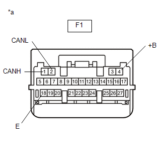
(a) Disconnect the cable from the negative (-) battery terminal.
(b) Disconnect the F1 certification ECU (smart key ECU assembly) connector.
(c) Measure the resistance according to the value(s) in the table below.
Standard Resistance:
|
Terminal No. (Symbol) |
Wiring Color |
Terminal Description |
Condition |
Specified Condition |
|---|---|---|---|---|
|
F1-1 (CANH) - F1-2 (CANL) |
R - SB |
HIGH-level CAN bus line - LOW-level CAN bus line |
Cable disconnected from negative (-) battery terminal |
54 to 69 Ω |
|
F1-1 (CANH) - F1-18 (E) |
R - W-B |
HIGH-level CAN bus line - Ground |
Cable disconnected from negative (-) battery terminal |
200 Ω or higher |
|
F1-2 (CANL) - F1-18 (E) |
SB - W-B |
LOW-level CAN bus line - Ground |
Cable disconnected from negative (-) battery terminal |
200 Ω or higher |
|
F1-1 (CANH) - F1-4 (+B) |
R - L |
HIGH-level CAN bus line - Battery positive (+) |
Cable disconnected from negative (-) battery terminal |
6 kΩ or higher |
|
F1-2 (CANL) - F1-4 (+B) |
SB - L |
LOW-level CAN bus line - Battery positive (+) |
Cable disconnected from negative (-) battery terminal |
6 kΩ or higher |
|
*a |
Front view of wire harness connector (to Certification ECU (Smart Key ECU Assembly)) |
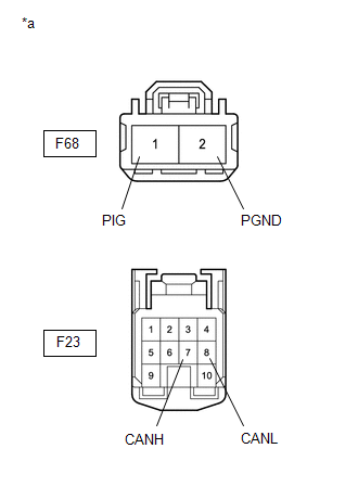
POWER STEERING ECU ASSEMBLY
Refer to Terminals of ECU.
Click here
(a) Disconnect the cable from the negative (-) battery terminal.
(b) Disconnect the F23 and F68 power steering ECU assembly connectors.
(c) Measure the resistance according to the value(s) in the table below.
|
*a |
Front view of wire harness connector (to Power Steering ECU Assembly) |
Standard Resistance:
|
Terminal No. (Symbol) |
Wiring Color |
Terminal Description |
Condition |
Specified Condition |
|---|---|---|---|---|
|
F23-7 (CANH) - F23-8 (CANL) |
P - W |
HIGH-level CAN bus line - LOW-level CAN bus line |
Cable disconnected from negative (-) battery terminal |
54 to 69 Ω |
|
F23-7 (CANH) - F68-2 (PGND) |
P - W-B |
HIGH-level CAN bus line - Ground |
Cable disconnected from negative (-) battery terminal |
200 Ω or higher |
|
F23-8 (CANL) - F68-2 (PGND) |
W - W-B |
LOW-level CAN bus line - Ground |
Cable disconnected from negative (-) battery terminal |
200 Ω or higher |
|
F23-7 (CANH) - F68-1 (PIG) |
P - B-W |
HIGH-level CAN bus line - Battery positive (+) |
Cable disconnected from negative (-) battery terminal |
6 kΩ or higher |
|
F23-8 (CANL) - F68-1 (PIG) |
W - B-W |
LOW-level CAN bus line - Battery positive (+) |
Cable disconnected from negative (-) battery terminal |
6 kΩ or higher |
AIRBAG SENSOR ASSEMBLY
Refer to Terminals of ECU.
Click here
(a) Disconnect the cable from the negative (-) battery terminal.
(b) Disconnect the F70 airbag sensor assembly connector.
(c) Measure the resistance according to the value(s) in the table below.
|
*1 |
DLC3 |
- |
- |
|
*a |
Front view of wire harness connector (to Airbag Sensor Assembly) |
- |
- |
Standard Resistance:
|
Terminal No. (Symbol) |
Wiring Color |
Terminal Description |
Condition |
Specified Condition |
|---|---|---|---|---|
|
F70-13 (CANH) - F70-22 (CANL) |
B - W |
HIGH-level CAN bus line - LOW-level CAN bus line |
Cable disconnected from negative (-) battery terminal |
108 to 132 Ω |
|
F70-13 (CANH) - F70-25 (E1) |
B - W-B |
HIGH-level CAN bus line - Ground |
Cable disconnected from negative (-) battery terminal |
200 Ω or higher |
|
F70-22 (CANL) - F70-25 (E1) |
W - W-B |
LOW-level CAN bus line - Ground |
Cable disconnected from negative (-) battery terminal |
200 Ω or higher |
|
F70-13 (CANH) - F41-16 (BAT) |
B - R |
HIGH-level CAN bus line - Battery positive (+) |
Cable disconnected from negative (-) battery terminal |
6 kΩ or higher |
|
F70-22 (CANL) - F41-16 (BAT) |
W - R |
LOW-level CAN bus line - Battery positive (+) |
Cable disconnected from negative (-) battery terminal |
6 kΩ or higher |
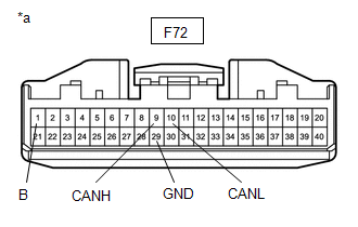
AIR CONDITIONING AMPLIFIER ASSEMBLY (w/ Top-mounted Air Conditioner Pressure Sensor)
Refer to Terminals of ECU.
Click here
(a) Disconnect the cable from the negative (-) battery terminal.
(b) Disconnect the F72 air conditioning amplifier assembly connector.
(c) Measure the resistance according to the value(s) in the table below.
Standard Resistance:
|
Terminal No. (Symbol) |
Wiring Color |
Terminal Description |
Condition |
Specified Condition |
|---|---|---|---|---|
|
F72-9 (CANH) - F72-10 (CANL) |
P - SB |
HIGH-level CAN bus line - LOW-level CAN bus line |
Cable disconnected from negative (-) battery terminal |
54 to 69 Ω |
|
F72-9 (CANH) - F72-29 (GND) |
P - W-B |
HIGH-level CAN bus line - Ground |
Cable disconnected from negative (-) battery terminal |
200 Ω or higher |
|
F72-10 (CANL) - F72-29 (GND) |
SB - W-B |
LOW-level CAN bus line - Ground |
Cable disconnected from negative (-) battery terminal |
200 Ω or higher |
|
F72-9 (CANH) - F72-1 (B) |
P - V |
HIGH-level CAN bus line - Battery positive (+) |
Cable disconnected from negative (-) battery terminal |
6 kΩ or higher |
|
F72-10 (CANL) - F72-1 (B) |
SB - V |
LOW-level CAN bus line - Battery positive (+) |
Cable disconnected from negative (-) battery terminal |
6 kΩ or higher |
|
*a |
Front view of wire harness connector (to Air Conditioning Amplifier Assembly) |
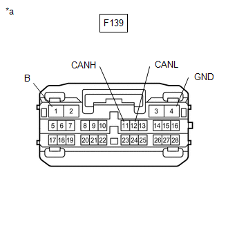
AIR CONDITIONING AMPLIFIER ASSEMBLY (w/ Side-mounted Air Conditioner Pressure Sensor)
Refer to Terminals of ECU.
Click here
(a) Disconnect the cable from the negative (-) battery terminal.
(b) Disconnect the F139 air conditioning amplifier assembly connector.
(c) Measure the resistance according to the value(s) in the table below.
Standard Resistance:
|
Terminal No. (Symbol) |
Wiring Color |
Terminal Description |
Condition |
Specified Condition |
|---|---|---|---|---|
|
F139-11 (CANH) - F139-12 (CANL) |
P - SB |
HIGH-level CAN bus line - LOW-level CAN bus line |
Cable disconnected from negative (-) battery terminal |
54 to 69 Ω |
|
F139-11 (CANH) - F139-4 (GND) |
P - W-B |
HIGH-level CAN bus line - Ground |
Cable disconnected from negative (-) battery terminal |
200 Ω or higher |
|
F139-12 (CANL) - F139-4 (GND) |
SB - W-B |
LOW-level CAN bus line - Ground |
Cable disconnected from negative (-) battery terminal |
200 Ω or higher |
|
F139-11 (CANH) - F139-1 (B) |
P - V |
HIGH-level CAN bus line - Battery positive (+) |
Cable disconnected from negative (-) battery terminal |
6 kΩ or higher |
|
F139-12 (CANL) - F139-1 (B) |
SB - V |
LOW-level CAN bus line - Battery positive (+) |
Cable disconnected from negative (-) battery terminal |
6 kΩ or higher |
|
*a |
Front view of wire harness connector (to Air Conditioning Amplifier Assembly) |
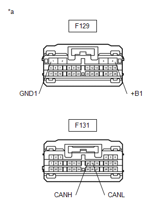
RADIO AND DISPLAY RECEIVER ASSEMBLY (for Radio and Display Type)
Refer to Terminals of ECU.
Click here
(a) Disconnect the cable from the negative (-) battery terminal.
(b) Disconnect the F129 and F131 radio and display receiver assembly connectors.
(c) Measure the resistance according to the value(s) in the table below.
|
*a |
Front view of wire harness connector (to Radio and Display Receiver Assembly) |
Standard Resistance:
|
Terminal No. (Symbol) |
Wiring Color |
Terminal Description |
Condition |
Specified Condition |
|---|---|---|---|---|
|
F131-13 (CANH) - F131-14 (CANL) |
B - LG |
HIGH-level CAN bus line - LOW-level CAN bus line |
Cable disconnected from negative (-) battery terminal |
54 to 69 Ω |
|
F131-13 (CANH) - F129-1 (GND1) |
B - LA |
HIGH-level CAN bus line - Ground |
Cable disconnected from negative (-) battery terminal |
200 Ω or higher |
|
F131-14 (CANL) - F129-1 (GND1) |
LG - LA |
LOW-level CAN bus line - Ground |
Cable disconnected from negative (-) battery terminal |
200 Ω or higher |
|
F131-13 (CANH) - F129-4 (+B1) |
B - LA-SB |
HIGH-level CAN bus line - Battery positive (+) |
Cable disconnected from negative (-) battery terminal |
6 kΩ or higher |
|
F131-14 (CANL) - F129-4 (+B1) |
LG - LA-SB |
LOW-level CAN bus line - Battery positive (+) |
Cable disconnected from negative (-) battery terminal |
6 kΩ or higher |
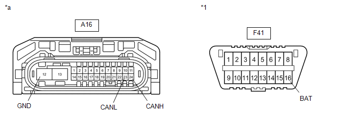
HEADLIGHT ECU SUB-ASSEMBLY LH (for LED Headlight)
Refer to Terminals of ECU.
Click here
(a) Disconnect the cable from the negative (-) battery terminal.
(b) Disconnect the A16 headlight ECU sub-assembly LH connector.
(c) Measure the resistance according to the value(s) in the table below.
|
*1 |
DLC3 |
- |
- |
|
*a |
Front view of wire harness connector (to Headlight ECU Sub-assembly LH) |
- |
- |
Standard Resistance:
|
Terminal No. (Symbol) |
Wiring Color |
Terminal Description |
Condition |
Specified Condition |
|---|---|---|---|---|
|
A16-24 (CANH) - A16-23 (CANL) |
L - SB |
HIGH-level CAN bus line - LOW-level CAN bus line |
Cable disconnected from negative (-) battery terminal |
54 to 69 Ω |
|
A16-24 (CANH) - A16-12 (GND) |
L - W-B |
HIGH-level CAN bus line - Ground |
Cable disconnected from negative (-) battery terminal |
200 Ω or higher |
|
A16-23 (CANL) - A16-12 (GND) |
SB - W-B |
LOW-level CAN bus line - Ground |
Cable disconnected from negative (-) battery terminal |
200 Ω or higher |
|
A16-24 (CANH) - F41-16 (BAT) |
L - R |
HIGH-level CAN bus line - Battery positive (+) |
Cable disconnected from negative (-) battery terminal |
6 kΩ or higher |
|
A16-23 (CANL) - F41-16 (BAT) |
SB - R |
LOW-level CAN bus line - Battery positive (+) |
Cable disconnected from negative (-) battery terminal |
6 kΩ or higher |
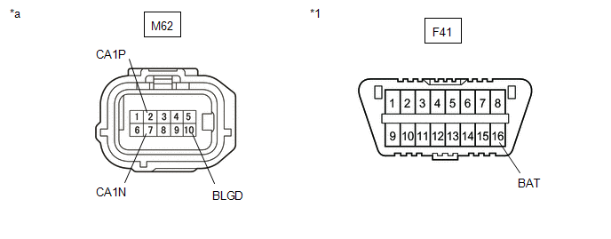
BLIND SPOT MONITOR SENSOR LH (w/ Blind Spot Monitor System)
Refer to Terminals of ECU.
Click here
(a) Disconnect the cable from the negative (-) battery terminal.
(b) Disconnect the M62 blind spot monitor sensor LH connector.
(c) Measure the resistance according to the value(s) in the table below.
|
*1 |
DLC3 |
- |
- |
|
*a |
Front view of wire harness connector (to Blind Spot Monitor Sensor LH) |
- |
- |
Standard Resistance:
|
Terminal No. (Symbol) |
Wiring Color |
Terminal Description |
Condition |
Specified Condition |
|---|---|---|---|---|
|
M62-2 (CA1P) - M62-7 (CA1N) |
G - GR |
HIGH-level CAN bus line - LOW-level CAN bus line |
Cable disconnected from negative (-) battery terminal |
54 to 69 Ω |
|
M62-2 (CA1P) - M62-10 (BLGD) |
G - W-B |
HIGH-level CAN bus line - Ground |
Cable disconnected from negative (-) battery terminal |
200 Ω or higher |
|
M62-7 (CA1N) - M62-10 (BLGD) |
GR - W-B |
LOW-level CAN bus line - Ground |
Cable disconnected from negative (-) battery terminal |
200 Ω or higher |
|
M62-2 (CA1P) - F41-16 (BAT) |
G - R |
HIGH-level CAN bus line - Battery positive (+) |
Cable disconnected from negative (-) battery terminal |
6 kΩ or higher |
|
M62-7 (CA1N) - F41-16 (BAT) |
GR - R |
LOW-level CAN bus line - Battery positive (+) |
Cable disconnected from negative (-) battery terminal |
6 kΩ or higher |
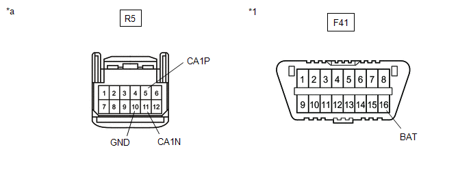
FORWARD RECOGNITION CAMERA (w/ Toyota Safety Sense P)
Refer to Terminals of ECU.
Click here
(a) Disconnect the cable from the negative (-) battery terminal.
(b) Disconnect the R5 forward recognition camera connector.
(c) Measure the resistance according to the value(s) in the table below.
|
*1 |
DLC3 |
- |
- |
|
*a |
Front view of wire harness connector (to Forward Recognition Camera) |
- |
- |
Standard Resistance:
|
Terminal No. (Symbol) |
Wiring Color |
Terminal Description |
Condition |
Specified Condition |
|---|---|---|---|---|
|
R5-5 (CA1P) - R5-11 (CA1N) |
R - GR |
HIGH-level CAN bus line - LOW-level CAN bus line |
Cable disconnected from negative (-) battery terminal |
54 to 69 Ω |
|
R5-5 (CA1P) - R5-10 (GND) |
R - W-B |
HIGH-level CAN bus line - Ground |
Cable disconnected from negative (-) battery terminal |
200 Ω or higher |
|
R5-11 (CA1N) - R5-10 (GND) |
GR - W-B |
LOW-level CAN bus line - Ground |
Cable disconnected from negative (-) battery terminal |
200 Ω or higher |
|
R5-5 (CA1P) - F41-16 (BAT) |
R - R |
HIGH-level CAN bus line - Battery positive (+) |
Cable disconnected from negative (-) battery terminal |
6 kΩ or higher |
|
R5-11 (CA1N) - F41-16 (BAT) |
GR - R |
LOW-level CAN bus line - Battery positive (+) |
Cable disconnected from negative (-) battery terminal |
6 kΩ or higher |
MILLIMETER WAVE RADAR SENSOR ASSEMBLY (w/ Toyota Safety Sense P)
Refer to Terminals of ECU.
Click here
(a) Disconnect the cable from the negative (-) battery terminal.
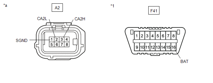
(b) Disconnect the A2 millimeter wave radar sensor assembly connector.
(c) Measure the resistance according to the value(s) in the table below.
|
*1 |
DLC3 |
- |
- |
|
*a |
Front view of wire harness connector (to Millimeter Wave Radar Sensor Assembly) |
- |
- |
Standard Resistance:
|
Terminal No. (Symbol) |
Wiring Color |
Terminal Description |
Condition |
Specified Condition |
|---|---|---|---|---|
|
A2-3 (CA2H) - A2-2 (CA2L) |
G - GR |
HIGH-level CAN bus line - LOW-level CAN bus line |
Cable disconnected from negative (-) battery terminal |
54 to 69 Ω |
|
A2-3 (CA2H) - A2-1 (SGND) |
G - W-B |
HIGH-level CAN bus line - Ground |
Cable disconnected from negative (-) battery terminal |
200 Ω or higher |
|
A2-2 (CA2L) - A2-1 (SGND) |
GR - W-B |
LOW-level CAN bus line - Ground |
Cable disconnected from negative (-) battery terminal |
200 Ω or higher |
|
A2-3 (CA2H) - F41-16 (BAT) |
G - R |
HIGH-level CAN bus line - Battery positive (+) |
Cable disconnected from negative (-) battery terminal |
6 kΩ or higher |
|
A2-2 (CA2L) - F41-16 (BAT) |
GR - R |
LOW-level CAN bus line - Battery positive (+) |
Cable disconnected from negative (-) battery terminal |
6 kΩ or higher |
OCCUPANT DETECTION ECU (w/ Occupant Detection ECU)
Refer to Terminals of ECU.
Click here
(a) Disconnect the cable from the negative (-) battery terminal.
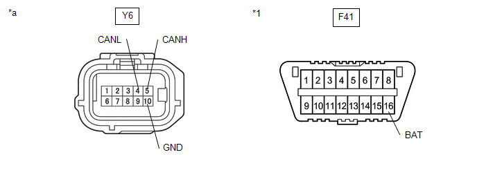
(b) Disconnect the Y6 occupant detection ECU connector.
(c) Measure the resistance according to the value(s) in the table below.
|
*1 |
DLC3 |
- |
- |
|
*a |
Front view of wire harness connector (to Occupant Detection ECU) |
- |
- |
Standard Resistance:
|
Terminal No. (Symbol) |
Wiring Color |
Terminal Description |
Condition |
Specified Condition |
|---|---|---|---|---|
|
Y6-5 (CANH) - Y6-4 (CANL) |
R - SB |
HIGH-level CAN bus line - LOW-level CAN bus line |
Cable disconnected from negative (-) battery terminal |
54 to 69 Ω |
|
Y6-5 (CANH) - Y6-10 (GND) |
R - W-B |
HIGH-level CAN bus line - Ground |
Cable disconnected from negative (-) battery terminal |
200 Ω or higher |
|
Y6-4 (CANL) - Y6-10 (GND) |
SB - W-B |
LOW-level CAN bus line - Ground |
Cable disconnected from negative (-) battery terminal |
200 Ω or higher |
|
Y6-5 (CANH) - F41-16 (BAT) |
R - R |
HIGH-level CAN bus line - Battery positive (+) |
Cable disconnected from negative (-) battery terminal |
6 kΩ or higher |
|
Y6-4 (CANL) - F41-16 (BAT) |
SB - R |
LOW-level CAN bus line - Battery positive (+) |
Cable disconnected from negative (-) battery terminal |
6 kΩ or higher |
DCM (TELEMATICS TRANSCEIVER) (w/ Telematics Transceiver)
Refer to Terminals of ECU.
Click here
(a) Disconnect the cable from the negative (-) battery terminal.
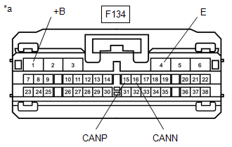
(b) Disconnect the F134 DCM (telematics transceiver) connector.
|
*a |
Front view of wire harness connector (to DCM (Telematics Transceiver)) |
(c) Measure the resistance according to the value(s) in the table below.
Standard Resistance:
|
Terminal No. (Symbol) |
Wiring Color |
Terminal Description |
Condition |
Specified Condition |
|---|---|---|---|---|
|
F134-15 (CANP) - F134-16 (CANN) |
GR - LG |
HIGH-level CAN bus line - LOW-level CAN bus line |
Cable disconnected from negative (-) battery terminal |
54 to 69 Ω |
|
F134-15 (CANP) - F134-4 (E) |
GR - W-B |
HIGH-level CAN bus line - Ground |
Cable disconnected from negative (-) battery terminal |
200 Ω or higher |
|
F134-16 (CANN) - F134-4 (E) |
LG - W-B |
LOW-level CAN bus line - Ground |
Cable disconnected from negative (-) battery terminal |
200 Ω or higher |
|
F134-15 (CANP) - F134-1 (+B) |
GR - W |
HIGH-level CAN bus line - Battery positive (+) |
Cable disconnected from negative (-) battery terminal |
6 kΩ or higher |
|
F134-16 (CANN) - F134-1 (+B) |
LG - W |
LOW-level CAN bus line - Battery positive (+) |
Cable disconnected from negative (-) battery terminal |
6 kΩ or higher |
 Problem Symptoms Table
PROBLEM SYMPTOMS TABLE
HINT:
Use the table below to help determine the cause of problem symptoms.
Inspect the fuses and relays related to this system before inspecting
the suspect ...
 Diagnosis System
DIAGNOSIS SYSTEM
CHECK FOR INSTALLED SYSTEMS (ECUS AND SENSORS) THAT USE CAN COMMUNICATION
(a) The systems (ECUs and sensors) that use CAN communication vary depending
on the vehicle and optional ...
Other materials:
Toyota CH-R Service Manual > Airbag System: Short in Front Pretensioner Squib LH Circuit (B1905/74-B1908/74)
DESCRIPTION
The front pretensioner squib LH circuit consists of the airbag sensor assembly
and front seat outer belt assembly LH.
The airbag sensor assembly uses this circuit to deploy the pretensioner when
deployment conditions are met.
These DTCs are stored when a malfunction is detected in ...
Toyota CH-R Service Manual > Brake Master Cylinder: Components
COMPONENTS
ILLUSTRATION
*1
COWL BODY MOUNTING REINFORCEMENT LH
*2
COWL BODY MOUNTING REINFORCEMENT RH
*3
NO. 1 HEATER AIR DUCT SPLASH SHIELD SEAL
*4
OUTER COWL TOP PANEL SUB-ASSEMBLY
*5 ...
Toyota C-HR (AX20) 2023-2026 Owner's Manual
Toyota CH-R Owners Manual
- For safety and security
- Instrument cluster
- Operation of each component
- Driving
- Interior features
- Maintenance and care
- When trouble arises
- Vehicle specifications
- For owners
Toyota CH-R Service Manual
- Introduction
- Maintenance
- Audio / Video
- Cellular Communication
- Navigation / Multi Info Display
- Park Assist / Monitoring
- Brake (front)
- Brake (rear)
- Brake Control / Dynamic Control Systems
- Brake System (other)
- Parking Brake
- Axle And Differential
- Drive Shaft / Propeller Shaft
- K114 Cvt
- 3zr-fae Battery / Charging
- Networking
- Power Distribution
- Power Assist Systems
- Steering Column
- Steering Gear / Linkage
- Alignment / Handling Diagnosis
- Front Suspension
- Rear Suspension
- Tire / Wheel
- Tire Pressure Monitoring
- Door / Hatch
- Exterior Panels / Trim
- Horn
- Lighting (ext)
- Mirror (ext)
- Window / Glass
- Wiper / Washer
- Door Lock
- Heating / Air Conditioning
- Interior Panels / Trim
- Lighting (int)
- Meter / Gauge / Display
- Mirror (int)
- Power Outlets (int)
- Pre-collision
- Seat
- Seat Belt
- Supplemental Restraint Systems
- Theft Deterrent / Keyless Entry

0.0156