Toyota CH-R Service Manual: Luggage Compartment Room Light
Components
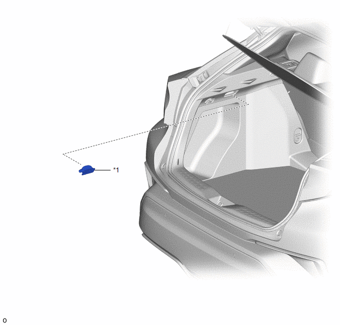
COMPONENTS
ILLUSTRATION
|
*1 |
NO. 1 LUGGAGE COMPARTMENT LIGHT ASSEMBLY |
- |
- |
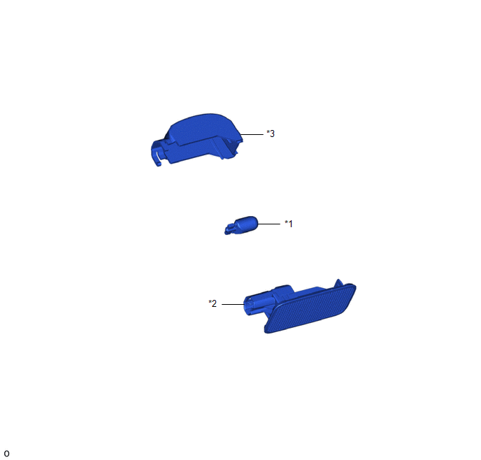
ILLUSTRATION
|
*1 |
LUGGAGE COMPARTMENT LIGHT BULB |
*2 |
LUGGAGE COMPARTMENT LIGHT LENS |
|
*3 |
LUGGAGE COMPARTMENT LIGHT SHADE |
- |
- |
Removal
REMOVAL
PROCEDURE
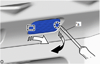
1. REMOVE NO. 1 LUGGAGE COMPARTMENT LIGHT ASSEMBLY
(a) Using a screwdriver with its tip wrapped in protective tape, disengage the claw and guide to remove the No. 1 luggage compartment light assembly as shown in the illustration.
|
*a |
Protective Tape |
.png) |
Remove in this Direction (1) |
.png) |
Remove in this Direction (2) |
2. REMOVE LUGGAGE COMPARTMENT LIGHT BULB
Click here .gif)
Installation
INSTALLATION
PROCEDURE
1. INSTALL LUGGAGE COMPARTMENT LIGHT BULB
Click here .gif)
2. INSTALL NO. 1 LUGGAGE COMPARTMENT LIGHT ASSEMBLY
(a) Engage the guide and claw to install the No. 1 luggage compartment light assembly as shown in the illustration.
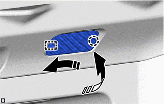
.png) |
Install in this Direction (1) |
.png) |
Install in this Direction (2) |
 Door Unlock Detection Switch Circuit
DESCRIPTION
The main body ECU (multiplex network body ECU) detects the condition of each
door unlock detection switch.
WIRING DIAGRAM
CAUTION / NOTICE / HINT
NOTICE:
Before replacing the main ...
 Luggage Compartment Room Light Bulb
Replacement
REPLACEMENT
PROCEDURE
1. REMOVE NO. 1 LUGGAGE COMPARTMENT LIGHT ASSEMBLY
Click here
2. REMOVE LUGGAGE COMPARTMENT LIGHT BULB
(a) Disengage the claws and guides to remove the lugg ...
Other materials:
Toyota CH-R Service Manual > Immobiliser System(w/o Smart Key System): How To Proceed With Troubleshooting
CAUTION / NOTICE / HINT
HINT:
Use this procedure to troubleshoot the immobiliser system.
*: Use the Techstream.
PROCEDURE
1.
VEHICLE BROUGHT TO WORKSHOP
NEXT
2.
...
Toyota CH-R Service Manual > Lin Communication System: Front Passenger Side Door ECU Communication Stop (B2322)
DESCRIPTION
This DTC is stored when LIN communication between the power window regulator
motor assembly (for front passenger door) and main body ECU (multiplex network body
ECU) stops for 10 seconds or more.
DTC No.
Detection Item
DTC Detection Condition
...
Toyota C-HR (AX20) 2023-2026 Owner's Manual
Toyota CH-R Owners Manual
- For safety and security
- Instrument cluster
- Operation of each component
- Driving
- Interior features
- Maintenance and care
- When trouble arises
- Vehicle specifications
- For owners
Toyota CH-R Service Manual
- Introduction
- Maintenance
- Audio / Video
- Cellular Communication
- Navigation / Multi Info Display
- Park Assist / Monitoring
- Brake (front)
- Brake (rear)
- Brake Control / Dynamic Control Systems
- Brake System (other)
- Parking Brake
- Axle And Differential
- Drive Shaft / Propeller Shaft
- K114 Cvt
- 3zr-fae Battery / Charging
- Networking
- Power Distribution
- Power Assist Systems
- Steering Column
- Steering Gear / Linkage
- Alignment / Handling Diagnosis
- Front Suspension
- Rear Suspension
- Tire / Wheel
- Tire Pressure Monitoring
- Door / Hatch
- Exterior Panels / Trim
- Horn
- Lighting (ext)
- Mirror (ext)
- Window / Glass
- Wiper / Washer
- Door Lock
- Heating / Air Conditioning
- Interior Panels / Trim
- Lighting (int)
- Meter / Gauge / Display
- Mirror (int)
- Power Outlets (int)
- Pre-collision
- Seat
- Seat Belt
- Supplemental Restraint Systems
- Theft Deterrent / Keyless Entry

0.0092