Toyota CH-R Service Manual: Short in Telephone Antenna Circuit (B1573,B15CB)
DESCRIPTION
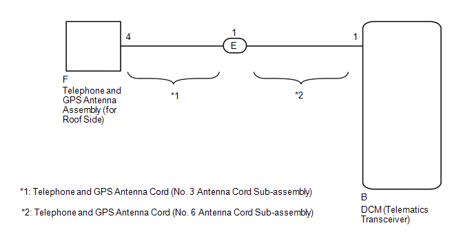
These DTCs are stored when the DCM (Telematics Transceiver) detects an open or a short in the telephone and GPS antenna assembly (for Roof Side) circuit. The DCM (Telematics Transceiver) oscillates and receives 824 - 894 MHz or 1850 - 1990 MHz radio-frequency through the telephone and GPS antenna assembly (for Roof Side).
|
DTC No. |
Detection Item |
DTC Detection Condition |
Trouble Area |
|---|---|---|---|
|
B1573 |
Short in Telephone Antenna Circuit |
Telephone and GPS antenna assembly (for Roof Side) impedance is lower than malfunction criterion for 10 seconds when ignition switch is ON. (Short circuit) |
|
|
B15CB |
Telematics Transceiver Antenna Disconnected |
Telephone and GPS antenna assembly (for Roof Side) impedance is higher than malfunction criterion for 10 seconds when ignition switch is ON. (Open circuit) |
|
WIRING DIAGRAM
CAUTION / NOTICE / HINT
HINT:
- Before performing this diagnostic procedure, make sure to perform Health
Check and confirm that the DCM/VIN registration information is correct.
Click here
.gif)
- Refer to "PARTS LOCATION" for the installation location of telephone
and GPS antenna cord.
Click here
PROCEDURE
|
1. |
CHECK DTC |
(a) Turn the ignition switch off.
(b) Connect the Techstream to the DLC3.
(c) Turn the ignition switch ON and wait for 10 seconds.
(d) Turn the Techstream on.
(e) Clear the DTCs.
Body Electrical > Telematics > Clear DTCs(f) Recheck for DTCs.
Body Electrical > Telematics > Trouble Codes|
Result |
Proceed to |
|---|---|
|
DTC B1573 or B15CB is output |
A |
|
DTC B1573 or B15CB is not output |
B |
| B | .gif) |
CHECK FOR INTERMITTENT PROBLEMS |
|
.gif)
|
2. |
INSPECT TELEPHONE AND GPS ANTENNA ASSEMBLY (for Roof Side) |
|
(a) Disconnect the F telephone and GPS antenna cord (No. 3 antenna cord sub-assembly) connector from the telephone and GPS antenna assembly (for Roof Side). |
|
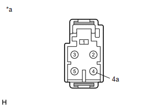
(b) Measure the resistance according to the value(s) in the table below.
Standard Resistance:
|
Tester Connection |
Condition |
Specified Condition |
|---|---|---|
|
4 - 4a |
Always |
4 to 11 kΩ |
| NG | |
REPLACE TELEPHONE AND GPS ANTENNA ASSEMBLY (for Roof Side) |
|
|
3. |
INSPECT TELEPHONE AND GPS ANTENNA CORD (NO. 3 ANTENNA CORD SUB-ASSEMBLY) |
|
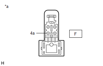
(a) Disconnect the F telephone and GPS antenna cord (No. 3 antenna cord sub-assembly) connector from the telephone and GPS antenna assembly (for Roof Side). |
|
|
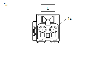
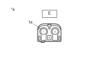
(b) Disconnect the E telephone and GPS antenna cord (No. 3 antenna cord sub-assembly) connector from the telephone and GPS antenna cord (No. 6 antenna cord sub-assembly). |
|
(c) Measure the resistance according to the value(s) in the table below.
Standard Resistance:
|
Tester Connection |
Condition |
Specified Condition |
|---|---|---|
|
F-4 - E-1 |
Always |
Below 1 Ω |
|
F-4 or E-1 - Body ground |
Always |
10 kΩ or higher |
|
F-4a - E-1a |
Always |
Below 1 Ω |
|
F-4a or E-1a - Body ground |
Always |
10 kΩ or higher |
| NG | |
REPLACE TELEPHONE AND GPS ANTENNA CORD (NO. 3 ANTENNA CORD SUB-ASSEMBLY) |
|
|
4. |
INSPECT TELEPHONE AND GPS ANTENNA CORD (NO. 6 ANTENNA CORD SUB-ASSEMBLY) |
|
(a) Disconnect the E telephone and GPS antenna cord (No. 6 antenna cord sub-assembly) connector from the telephone and GPS antenna cord (No. 3 antenna cord sub-assembly). |
|
|
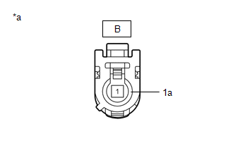
(b) Disconnect the B telephone and GPS antenna cord (No. 6 antenna cord sub-assembly) connector from the telematics transceiver. |
|
(c) Measure the resistance according to the value(s) in the table below.
Standard Resistance:
|
Tester Connection |
Condition |
Specified Condition |
|---|---|---|
|
E-1 - B-1 |
Always |
Below 1 Ω |
|
E-1 or B-1 - Body ground |
Always |
10 kΩ or higher |
|
E-1a - B-1a |
Always |
Below 1 Ω |
|
E-1a or B-1a - Body ground |
Always |
10 kΩ or higher |
| NG | |
REPLACE TELEPHONE AND GPS ANTENNA CORD (NO. 6 ANTENNA CORD SUB-ASSEMBLY) |
|
|
5. |
REPLACE TELEPHONE AND GPS ANTENNA ASSEMBLY (for Roof Side) |
(a) Replace the telephone and GPS antenna assembly (for Roof Side) with a known good one and check if the same problem occurs again.
Click here
OK:
The system returns to normal.
| OK | |
END |
|
|
6. |
REPLACE DCM (TELEMATICS TRANSCEIVER) |
(a) Replace the DCM (Telematics Transceiver).
Click here
NOTICE:
- The ignition switch must be off.
- Do not swap the DCM (Telematics Transceiver) with one from another vehicle.
| NEXT | |
PERFORM DCM ACTIVATION |
 Telematics Transceiver Malfunction (B15A8)
DESCRIPTION
This DTC is set when an error in the EEPROM or PLL IC is detected on the DCM
(Telematics Transceiver) self-check. The EEPROM (Electrically Erasable Programmable
Read-Only Memory) stor ...
 Backup Battery Failure (B15CC)
DESCRIPTION
This DTC is set when the DCM (Telematics Transceiver) detects one of the following:
The BUB (Back-Up Battery) voltage drops or the BUB (Back-Up Battery)
malfunctions.
The ...
Other materials:
Toyota CH-R Service Manual > Safety Connect System: Parts Location
PARTS LOCATION
ILLUSTRATION
*A
w/ Navigation System
-
-
*1
RADIO AND DISPLAY RECEIVER ASSEMBLY
*2
INSTRUMENT PANEL JUNCTION BLOCK ASSEMBLY
- ECU-ACC FUSE
- ECU-IG2 NO. 3 FUSE
*3
...
Toyota CH-R Service Manual > Audio And Visual System(for Radio And Display Type): Speaker Output Short (B15C3)
DESCRIPTION
This DTC is stored when a malfunction occurs in the speakers.
DTC No.
Detection Item
DTC Detection Condition
Trouble Area
B15C3
Speaker Output Short
A short is detected in the speaker output circuit
...
Toyota C-HR (AX20) 2023-2026 Owner's Manual
Toyota CH-R Owners Manual
- For safety and security
- Instrument cluster
- Operation of each component
- Driving
- Interior features
- Maintenance and care
- When trouble arises
- Vehicle specifications
- For owners
Toyota CH-R Service Manual
- Introduction
- Maintenance
- Audio / Video
- Cellular Communication
- Navigation / Multi Info Display
- Park Assist / Monitoring
- Brake (front)
- Brake (rear)
- Brake Control / Dynamic Control Systems
- Brake System (other)
- Parking Brake
- Axle And Differential
- Drive Shaft / Propeller Shaft
- K114 Cvt
- 3zr-fae Battery / Charging
- Networking
- Power Distribution
- Power Assist Systems
- Steering Column
- Steering Gear / Linkage
- Alignment / Handling Diagnosis
- Front Suspension
- Rear Suspension
- Tire / Wheel
- Tire Pressure Monitoring
- Door / Hatch
- Exterior Panels / Trim
- Horn
- Lighting (ext)
- Mirror (ext)
- Window / Glass
- Wiper / Washer
- Door Lock
- Heating / Air Conditioning
- Interior Panels / Trim
- Lighting (int)
- Meter / Gauge / Display
- Mirror (int)
- Power Outlets (int)
- Pre-collision
- Seat
- Seat Belt
- Supplemental Restraint Systems
- Theft Deterrent / Keyless Entry

0.0087