Toyota CH-R Service Manual: Disposal
DISPOSAL
CAUTION / NOTICE / HINT
CAUTION:
Before performing pre-disposal deployment of any SRS part, review and closely follow all applicable environmental and hazardous material regulations. Pre-disposal deployment may be considered hazardous material treatment.
PROCEDURE
1. PRECAUTION
CAUTION:
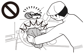
- An airbag or pretensioner may be activated by static electricity. To prevent this, be sure to touch a metal surface with your bare hands to discharge static electricity before performing this procedure.
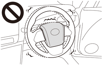
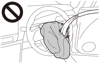
- Never dispose of a horn button assembly with an undeployed airbag.
- The airbag produces an exploding sound when it is deployed, so perform
the operation outdoors where it will not disturb nearby residents.
.png)
- When deploying the airbag, always use the specified SST (SRS airbag deployment tool). Perform the operation in a place away from electrical noise.
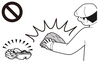
- When deploying the airbag, perform the operation at least 10 m (32.8 ft.) away from the horn button assembly.
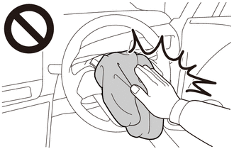
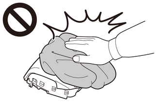
- The horn button assembly becomes extremely hot when the airbag is deployed, so do not touch it for at least 30 minutes after deployment.
- Use gloves and safety glasses when handling a horn button assembly with a deployed airbag.
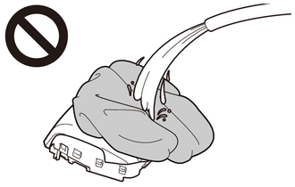
- Do not apply water, etc. to a horn button assembly with a deployed airbag.
- Always wash your hands with water after completing the operation.
HINT:
When scrapping a vehicle equipped with an SRS or disposing of the horn button assembly, be sure to deploy the airbag first in accordance with the procedure described below. If any abnormality occurs with the airbag deployment, contact the service department of TOYOTA MOTOR SALES, U.S.A., INC.
2. DISPOSE OF HORN BUTTON ASSEMBLY (When Installed to Vehicle)
NOTICE:
- When disposing of the horn button assembly, never use the customer's vehicle to deploy the airbag.
- Be sure to observe the following procedure when deploying the airbag.
HINT:
Prepare a battery as the power source to deploy the airbag.
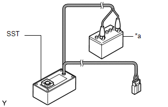
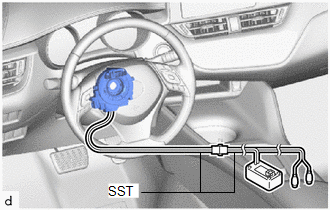
(a) Check the function of SST.
.png)
SST: 09082-00700
CAUTION:
When deploying the airbag, always use the specified SST:
SRS airbag deployment tool
|
(1) Connect SST to the battery. Connect the red clip of SST to the positive (+) battery terminal and the black clip of SST to the negative (-) battery terminal. |
|
|
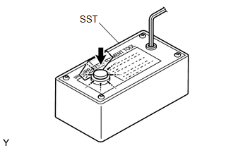
(2) Check the function of SST. Press the SST activation switch and check that the LED of the SST activation switch comes on. CAUTION:
|
|
(3) Disconnect SST from the battery.
(b) Refer to Precaution.
Click here .gif)
(c) Remove the lower steering column cover sub-assembly.
Click here
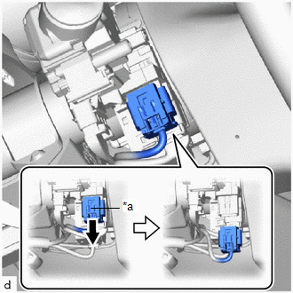
(d) Disconnect the airbag connector from the spiral cable with sensor sub-assembly.
|
(1) Slide the slider to release the lock, and then disconnect the airbag connector from the spiral cable with sensor sub-assembly. NOTICE: When disconnecting any airbag connector, take care not to damage the airbag wire harness. |
|
(e) Install SST.
CAUTION:
Check that there is no looseness in the steering wheel assembly or horn button assembly.
|
(1) After connecting the following SST to each other, connect them to the spiral cable with sensor sub-assembly. SST: 09082-00700 SST: 09082-00780 NOTICE: To avoid damaging the SST connector or wire harness, do not lock the secondary lock of the twin lock. |
|
|
(2) Move SST at least 10 m (32.8 ft.) away from the front side window of the vehicle. |
|
.png)
(3) Maintaining sufficient clearance for the SST wire harness in the front side window, close all doors and windows of the vehicle.
NOTICE:
Take care not to damage the SST wire harness.
(4) Connect the red clip of SST to the positive (+) battery terminal and the black clip of SST to the negative (-) battery terminal.
(f) Deploy the airbag.
(1) Check that no one is inside the vehicle or within a 10 m (32.8 ft.) radius of the vehicle.
(2) Press the SST activation switch to deploy the airbag.
CAUTION:
- Before deployment, make sure that no one is inside or near the vehicle.
.png)
- The horn button assembly becomes extremely hot when the airbag is deployed,
so do not touch it for at least 30 minutes after deployment.
- Use gloves and safety glasses when handling a horn button assembly with
a deployed airbag.
- Do not apply water, etc. to a horn button assembly with a deployed airbag.
- Always wash your hands with water after completing the operation.
HINT:
The airbag is deployed as the LED of the SST activation switch comes on.
3. DISPOSE OF HORN BUTTON ASSEMBLY (When not Installed to Vehicle)
NOTICE:
Be sure to observe the following procedure when deploying the airbag.
HINT:
Prepare a battery as the power source to deploy the airbag.
(a) Check the function of SST.
SST: 09082-00700
CAUTION:
When deploying the airbag, always use the specified SST:
SRS airbag deployment tool
|
(1) Connect SST to the battery. Connect the red clip of SST to the positive (+) battery terminal and the black clip of SST to the negative (-) battery terminal. |
|
|
(2) Check the function of SST. Press the SST activation switch and check that the LED of the SST activation switch comes on. CAUTION:
|
|
(3) Disconnect SST from the battery.
(b) Remove the horn button assembly.
Click here
CAUTION:
- Before removing the horn button assembly, wait at least 90 seconds after
turning the ignition switch off and disconnecting the cable from the negative
(-) battery terminal.
.png)
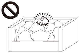
- When storing the horn button assembly, keep the airbag deployment side
facing upward.
.png)
.png)
Deployment Side
.png)
|
*a |
Wire Diameter |
|
*b |
Stripped Wire Cross Sectional Area |
(c) Using braided wire, tie down the horn button assembly to an unneeded tire and wheel set.
Wire:
Stripped wire cross sectional area
1.25 mm2 (0.0019 in.2) or more
CAUTION:
If the wire is too thin or an alternative object is used to tie down the horn button assembly, it may snap when the airbag is deployed. Always use a wire for vehicle use with a cross sectional area of at least 1.25 mm2 (0.0019 in.2).
HINT:
To calculate the cross sectional area of the stripped wire:
Cross sectional area = 3.14 x (Diameter)2 / 4
|
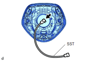
(1) Connect SST to the horn button assembly (for Single Type). SST: 09082-00830 |
|
|
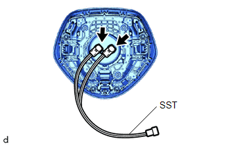
(2) Connect SST to the horn button assembly (for Dual Type). SST: 09082-00840 |
|
|
(3) Wind 2 wires around the omega springs at least 2 times each. CAUTION: Tightly wind the wires around the omega springs without any slack. |
|
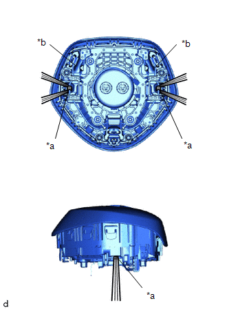
(4) Face the airbag deployment side of the horn button assembly upward on top of an unneeded tire and wheel set. Separately tie each side of the horn button assembly to the wheel through the hub nut holes. Position the SST connector so that it hangs downward through the hub hole of the wheel.
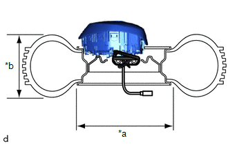
|
*a |
Inner Diameter |
|
*b |
Width |
Minimum tire size:
Width
185 mm (7.28 in.)
Inner diameter
360 mm (1.18 ft.)
CAUTION:
- Make sure that the wires are tight. If there is slack in the wires, the horn button assembly may break loose when the airbag is deployed.
- Always tie down the horn button assembly with the airbag deployment
side facing upward.
Deployment Side
NOTICE:
The wheel and tire may be damaged by the airbag deployment, so use an unneeded tire and wheel set.
(d) Install SST.
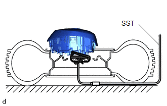
CAUTION:
Place the tire and wheel set on level ground.
(1) Connect the SST connector.
SST: 09082-00700
NOTICE:
To avoid damaging the SST connector or wire harness, do not lock the secondary lock of the twin lock. Also, secure some slack for the SST wire harness inside the wheel.
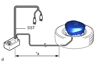
|
(2) Move SST at least 10 m (32.8 ft.) away from the airbag tied down to the tire and wheel set. |
|
(e) Cover the horn button assembly (using a cardboard box).
|
(1) Cover the horn button assembly with a cardboard box. |
|
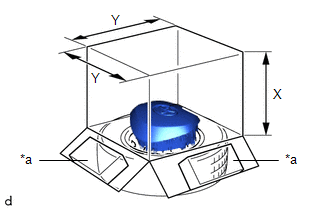
(2) Place weights on the cardboard box in 4 places totaling at least 190 N (19 kg, 42.7 lb).
Minimum cardboard box size:
X
460 mm (1.51 ft.)
Y
650 mm (2.13 ft.)
NOTICE:
- When dimension Y of the cardboard box exceeds the diameter of the wheel
and tire to which the horn button assembly is tied, X should be the following
size.
X = 460 mm (1.51 ft.) + width of tire
- If a cardboard box smaller than the specified size is used, it may be broken by the shock of the airbag deployment.
(f) Cover the horn button assembly (using tires).
|
(1) Place at least 3 tires without wheels onto the tire and wheel set to which the horn button assembly is tied. |
|
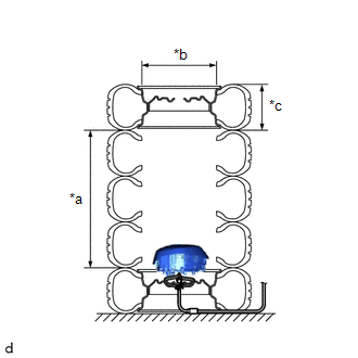
(2) Place a tire and wheel set on top.
Minimum tire size:
Width
185 mm (7.28 in.)
Inner diameter
360 mm (1.18 ft.)
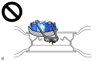
CAUTION:
Do not use tires with wheels except on the top and bottom.
NOTICE:
- The wheels and tires may be damaged by the airbag deployment, so use unneeded wheels and tires.
- Do not place the SST connector under the tire because it could be damaged.
|
(3) Tie the tires together with 2 wires. CAUTION: Make sure that the wires are tight. Looseness in the wires will result in the tires breaking loose when the airbag is deployed. |
|
.png)
(g) Deploy the airbag.
|
(1) Connect the red clip of SST to the positive (+) battery terminal and the black clip of SST to the negative (-) battery terminal. |
|
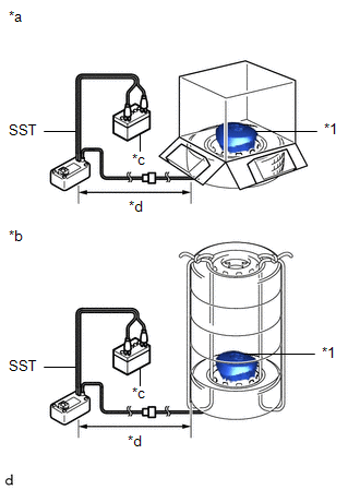
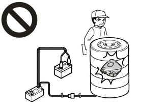
(2) Check that no one is within a 10 m (32.8 ft.) radius of the wheel to which the horn button assembly is tied.
(3) Press the SST activation switch to deploy the airbag.
CAUTION:
Before deployment, make sure that no one is near the airbag.
HINT:
The airbag is deployed as the LED of the SST activation switch comes on.
(h) Dispose of the horn button assembly.
CAUTION:
- The horn button assembly becomes extremely hot when the airbag is deployed,
so do not touch it for at least 30 minutes after deployment.
- Use gloves and safety glasses when handling a horn button assembly with
a deployed airbag.
- Do not apply water, etc. to a horn button assembly with a deployed airbag.
- Always wash your hands with water after completing the operation.
(1) Remove the horn button assembly from the tire and wheel set.
(2) Place the horn button assembly in a plastic bag, tie it tightly and dispose of it according to local regulations.
 Removal
REMOVAL
CAUTION / NOTICE / HINT
The necessary procedures (adjustment, calibration, initialization, or registration)
that must be performed after parts are removed, installed, or replaced during th ...
 Installation
INSTALLATION
PROCEDURE
1. INSTALL HORN BUTTON ASSEMBLY
(a) Check that the ignition switch off.
(b) Check that the cable is disconnected from the negative (-) battery terminal.
CAUTION:
Wait at l ...
Other materials:
Toyota CH-R Service Manual > Transmission Control Cable: Precaution
PRECAUTION
IGNITION SWITCH EXPRESSIONS
(a) The type of ignition switch used on this model differs depending on the specifications
of the vehicle. The expressions listed in the table below are used in this section.
Expression
Ignition Switch (Position)
Engine Swi ...
Toyota CH-R Service Manual > Pre-collision System: System Diagram
SYSTEM DIAGRAM
Communication Table
Sender
Receiver
Signal
Line
Millimeter Wave Radar Sensor Assembly
Skid Control ECU (Brake Actuator Assembly)
Brake assist standby signal
Pre-collision brake ope ...
Toyota C-HR (AX20) 2023-2026 Owner's Manual
Toyota CH-R Owners Manual
- For safety and security
- Instrument cluster
- Operation of each component
- Driving
- Interior features
- Maintenance and care
- When trouble arises
- Vehicle specifications
- For owners
Toyota CH-R Service Manual
- Introduction
- Maintenance
- Audio / Video
- Cellular Communication
- Navigation / Multi Info Display
- Park Assist / Monitoring
- Brake (front)
- Brake (rear)
- Brake Control / Dynamic Control Systems
- Brake System (other)
- Parking Brake
- Axle And Differential
- Drive Shaft / Propeller Shaft
- K114 Cvt
- 3zr-fae Battery / Charging
- Networking
- Power Distribution
- Power Assist Systems
- Steering Column
- Steering Gear / Linkage
- Alignment / Handling Diagnosis
- Front Suspension
- Rear Suspension
- Tire / Wheel
- Tire Pressure Monitoring
- Door / Hatch
- Exterior Panels / Trim
- Horn
- Lighting (ext)
- Mirror (ext)
- Window / Glass
- Wiper / Washer
- Door Lock
- Heating / Air Conditioning
- Interior Panels / Trim
- Lighting (int)
- Meter / Gauge / Display
- Mirror (int)
- Power Outlets (int)
- Pre-collision
- Seat
- Seat Belt
- Supplemental Restraint Systems
- Theft Deterrent / Keyless Entry

0.0077