Toyota CH-R Service Manual: System Diagram
SYSTEM DIAGRAM
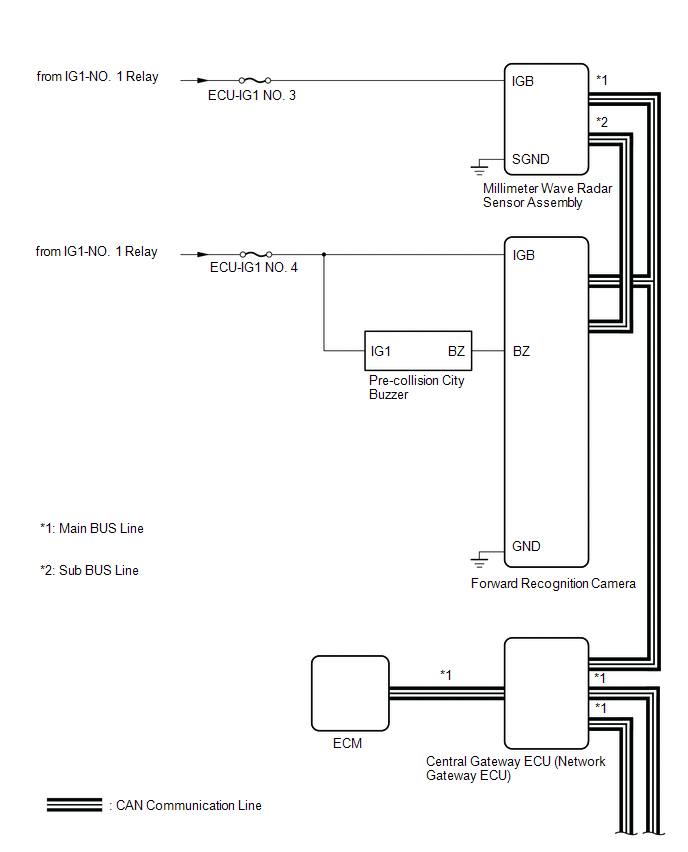
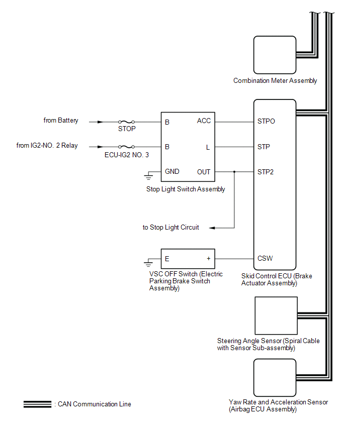 Communication Table
|
Sender |
Receiver |
Signal |
Line |
|---|---|---|---|
|
Millimeter Wave Radar Sensor Assembly |
Skid Control ECU (Brake Actuator Assembly) |
|
CAN |
|
Millimeter Wave Radar Sensor Assembly |
Combination Meter Assembly |
|
CAN |
|
Millimeter Wave Radar Sensor Assembly |
Forward Recognition Camera |
|
CAN |
|
Millimeter Wave Radar Sensor Assembly |
ECM |
Throttle valve close signal |
CAN |
|
Forward Recognition Camera |
Millimeter Wave Radar Sensor Assembly |
|
CAN |
|
Skid Control ECU (Brake Actuator Assembly) |
Millimeter Wave Radar Sensor Assembly |
|
CAN |
|
Skid Control ECU (Brake Actuator Assembly) |
Forward Recognition Camera |
Vehicle speed signal |
CAN |
|
Skid Control ECU (Brake Actuator Assembly) |
Combination Meter Assembly |
|
CAN |
|
Yaw Rate and Acceleration Sensor (Airbag Sensor Assembly) |
Millimeter Wave Radar Sensor Assembly |
Vehicle yaw rate and acceleration sensor signal |
CAN |
|
Yaw Rate and Acceleration Sensor (Airbag Sensor Assembly) |
Forward Recognition Camera |
Vehicle yaw rate and acceleration sensor signal |
CAN |
|
Steering Angle Sensor (Spiral Cable with Sensor Sub-assembly) |
Millimeter Wave Radar Sensor Assembly |
|
CAN |
|
Steering Angle Sensor (Spiral Cable with Sensor Sub-assembly) |
Forward Recognition Camera |
Steering angle sensor malfunction signal |
CAN |
|
ECM |
Millimeter Wave Radar Sensor Assembly |
|
CAN |
 Parts Location
PARTS LOCATION
ILLUSTRATION
*1
FRONT SPEED SENSOR RH
*2
FRONT SPEED SENSOR LH
*3
REAR SKID CONTROL SENSOR RH
*4
...
 How To Proceed With Troubleshooting
CAUTION / NOTICE / HINT
HINT:
Use these procedures to troubleshoot the pre-collision system.
*: Use the Techstream.
PROCEDURE
1.
VEHICLE BROUGHT TO WORKSHO ...
Other materials:
Toyota CH-R Service Manual > Power Window Control System: Driver Side Power Window does not Operate with Power Window Master Switch
DESCRIPTION
When the ignition switch is ON, the power window regulator motor assembly (for
driver door) is operated by the multiplex network master switch assembly. The power
window regulator motor assembly (for driver door) has motor, regulator and ECU functions.
WIRING DIAGRAM
CAUTION / N ...
Toyota CH-R Service Manual > Blind Spot Monitor System: Master Module Horizontal Axis Misalignment (C1AC1)
DESCRIPTION
This DTC is stored when the angle of the blind spot monitor sensor LH (Master)
deviates more than the allowable range from the horizontal axis.
HINT:
If a drum tester such as a speedometer tester, brake/speedometer combination
tester or chassis dynamometer is used with t ...
Toyota C-HR (AX20) 2023-2026 Owner's Manual
Toyota CH-R Owners Manual
- For safety and security
- Instrument cluster
- Operation of each component
- Driving
- Interior features
- Maintenance and care
- When trouble arises
- Vehicle specifications
- For owners
Toyota CH-R Service Manual
- Introduction
- Maintenance
- Audio / Video
- Cellular Communication
- Navigation / Multi Info Display
- Park Assist / Monitoring
- Brake (front)
- Brake (rear)
- Brake Control / Dynamic Control Systems
- Brake System (other)
- Parking Brake
- Axle And Differential
- Drive Shaft / Propeller Shaft
- K114 Cvt
- 3zr-fae Battery / Charging
- Networking
- Power Distribution
- Power Assist Systems
- Steering Column
- Steering Gear / Linkage
- Alignment / Handling Diagnosis
- Front Suspension
- Rear Suspension
- Tire / Wheel
- Tire Pressure Monitoring
- Door / Hatch
- Exterior Panels / Trim
- Horn
- Lighting (ext)
- Mirror (ext)
- Window / Glass
- Wiper / Washer
- Door Lock
- Heating / Air Conditioning
- Interior Panels / Trim
- Lighting (int)
- Meter / Gauge / Display
- Mirror (int)
- Power Outlets (int)
- Pre-collision
- Seat
- Seat Belt
- Supplemental Restraint Systems
- Theft Deterrent / Keyless Entry

0.0091