Toyota CH-R Service Manual: Parts Location
PARTS LOCATION
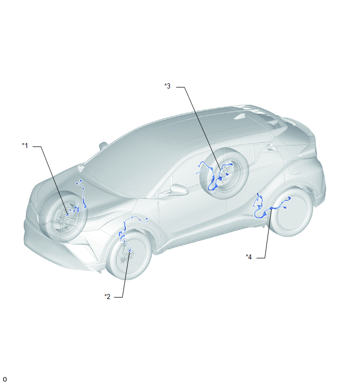
ILLUSTRATION
|
*1 |
FRONT SPEED SENSOR RH |
*2 |
FRONT SPEED SENSOR LH |
|
*3 |
REAR SKID CONTROL SENSOR RH |
*4 |
REAR SKID CONTROL SENSOR LH |
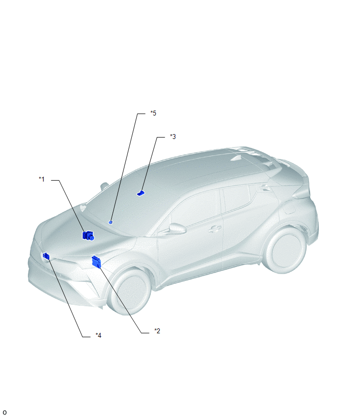
ILLUSTRATION
|
*1 |
BRAKE ACTUATOR ASSEMBLY - SKID CONTROL ECU |
*2 |
ECM |
|
*3 |
FORWARD RECOGNITION CAMERA |
*4 |
MILLIMETER WAVE RADAR SENSOR ASSEMBLY |
|
*5 |
PRE-COLLISION CITY BUZZER |
- |
- |
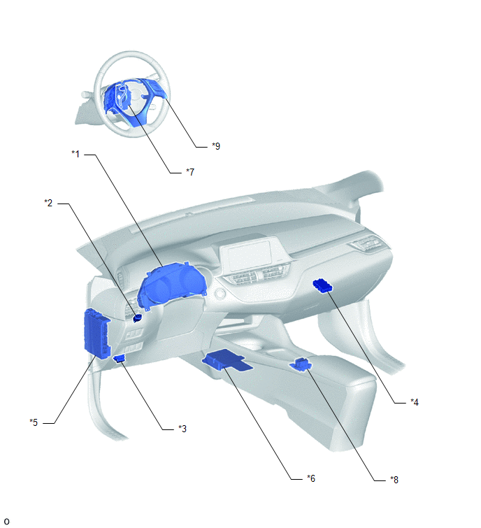
ILLUSTRATION
|
*1 |
COMBINATION METER ASSEMBLY |
*2 |
STOP LIGHT SWITCH ASSEMBLY |
|
*3 |
DLC3 |
*4 |
CENTRAL GATEWAY ECU (NETWORK GATEWAY ECU) |
|
*5 |
INSTRUMENT PANEL JUNCTION BLOCK ASSEMBLY - IG1-NO. 1 Relay - ECU-IG1 NO. 3 FUSE - ECU-IG1 NO. 4 FUSE - IG2-NO. 2 Relay - ECU-IG2 NO. 3 FUSE |
*6 |
AIRBAG SENSOR ASSEMBLY - YAW RATE AND ACCELERATION SENSOR |
|
*7 |
SPIRAL CABLE WITH SENSOR SUB-ASSEMBLY - STEERING ANGLE SENSOR |
*8 |
ELECTRIC PARKING BRAKE SWITCH ASSEMBLY - VSC OFF SWITCH |
|
*9 |
STEERING PAD SWITCH ASSEMBLY |
- |
- |
 Precaution
PRECAUTION
IGNITION SWITCH EXPRESSION
(a) The type of ignition switch used on this model differs depending on the specifications
of the vehicle. The expressions listed in the table below are used ...
 System Diagram
SYSTEM DIAGRAM
Communication Table
Sender
Receiver
Signal
Line
Millimeter Wave Radar Sensor Assembly
Skid Control ECU (Brak ...
Other materials:
Toyota CH-R Service Manual > Vacuum Pump: Disassembly
DISASSEMBLY
PROCEDURE
1. REMOVE END COVER
(a) Using a T25 "TORX" socket wrench, remove the 5 screws and end cover.
NOTICE:
Hold the vacuum pump assembly so that its installation surface,
fitting parts and oil pipe will not be damaged.
As the vac ...
Toyota CH-R Service Manual > Front Airbag Sensor: On-vehicle Inspection
ON-VEHICLE INSPECTION
CAUTION / NOTICE / HINT
CAUTION:
Be sure to correctly follow the removal and installation procedures for the front
airbag sensors.
PROCEDURE
1. INSPECT FRONT AIRBAG SENSOR (for Vehicle not Involved in Collision)
(a) Perform a diagnostic system check.
Click here
2. I ...
Toyota C-HR (AX20) 2023-2026 Owner's Manual
Toyota CH-R Owners Manual
- For safety and security
- Instrument cluster
- Operation of each component
- Driving
- Interior features
- Maintenance and care
- When trouble arises
- Vehicle specifications
- For owners
Toyota CH-R Service Manual
- Introduction
- Maintenance
- Audio / Video
- Cellular Communication
- Navigation / Multi Info Display
- Park Assist / Monitoring
- Brake (front)
- Brake (rear)
- Brake Control / Dynamic Control Systems
- Brake System (other)
- Parking Brake
- Axle And Differential
- Drive Shaft / Propeller Shaft
- K114 Cvt
- 3zr-fae Battery / Charging
- Networking
- Power Distribution
- Power Assist Systems
- Steering Column
- Steering Gear / Linkage
- Alignment / Handling Diagnosis
- Front Suspension
- Rear Suspension
- Tire / Wheel
- Tire Pressure Monitoring
- Door / Hatch
- Exterior Panels / Trim
- Horn
- Lighting (ext)
- Mirror (ext)
- Window / Glass
- Wiper / Washer
- Door Lock
- Heating / Air Conditioning
- Interior Panels / Trim
- Lighting (int)
- Meter / Gauge / Display
- Mirror (int)
- Power Outlets (int)
- Pre-collision
- Seat
- Seat Belt
- Supplemental Restraint Systems
- Theft Deterrent / Keyless Entry

0.0076