Toyota CH-R Service Manual: Parts Location
PARTS LOCATION
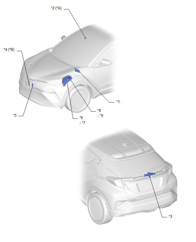
ILLUSTRATION
|
*A |
w/ Rain Sensor |
*B |
for Cold Area Specification Vehicles |
|
*1 |
WINDSHIELD WIPER MOTOR ASSEMBLY |
*2 |
RAIN SENSOR |
|
*3 |
REAR WIPER MOTOR ASSEMBLY |
*4 |
LEVEL WARNING SWITCH ASSEMBLY |
|
*5 |
WINDSHIELD WASHER MOTOR AND PUMP ASSEMBLY |
*6 |
NO. 1 ENGINE ROOM RELAY BLOCK |
|
*7 |
WIPER FUSE |
*8 |
NO. 1 INTEGRATION RELAY |
|
*9 |
IG1-NO. 3 RELAY |
- |
- |
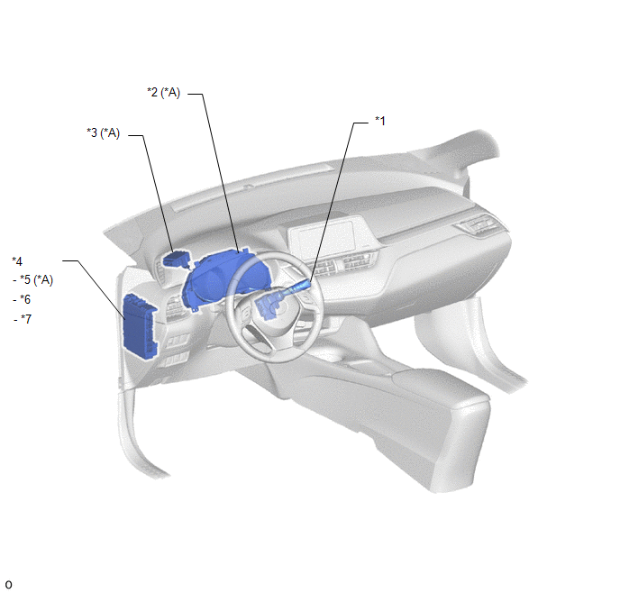
ILLUSTRATION
|
*A |
w/ Rain Sensor |
- |
- |
|
*1 |
WINDSHIELD WIPER SWITCH ASSEMBLY |
*2 |
COMBINATION METER ASSEMBLY |
|
*3 |
WINDSHIELD WIPER RELAY ASSEMBLY |
*4 |
INSTRUMENT PANEL JUNCTION BLOCK ASSEMBLY |
|
*5 |
ECU-IG1 NO. 4 FUSE |
*6 |
WASHER FUSE |
|
*7 |
WIPER RR FUSE |
- |
- |
 Precaution
PRECAUTION
IGNITION SWITCH EXPRESSIONS
(a) The type of ignition switch used on this model differs according to the specifications
of the vehicle. The expressions listed in the table below are used ...
 System Description
SYSTEM DESCRIPTION
FRONT WIPER AND WASHER CONTROL FUNCTION
Control/Function
Description
MIST function
Operates the wipers in the LO setting when the ...
Other materials:
Toyota CH-R Service Manual > Steering Pad: Disposal
DISPOSAL
CAUTION / NOTICE / HINT
CAUTION:
Before performing pre-disposal deployment of any SRS part, review and closely
follow all applicable environmental and hazardous material regulations. Pre-disposal
deployment may be considered hazardous material treatment.
PROCEDURE
1. PRECAUTION
...
Toyota CH-R Service Manual > Navigation System: Vehicle Speed Signal Circuit between Radio Receiver and Combination Meter
DESCRIPTION
for Automatic Sound Levelizer (ASL):
This circuit is necessary for the Automatic Sound Levelizer (ASL) built
into the radio and display receiver assembly.
The Automatic Sound Levelizer (ASL) function automatically adjusts the
audio system volume level in order to com ...
Toyota C-HR (AX20) 2023-2026 Owner's Manual
Toyota CH-R Owners Manual
- For safety and security
- Instrument cluster
- Operation of each component
- Driving
- Interior features
- Maintenance and care
- When trouble arises
- Vehicle specifications
- For owners
Toyota CH-R Service Manual
- Introduction
- Maintenance
- Audio / Video
- Cellular Communication
- Navigation / Multi Info Display
- Park Assist / Monitoring
- Brake (front)
- Brake (rear)
- Brake Control / Dynamic Control Systems
- Brake System (other)
- Parking Brake
- Axle And Differential
- Drive Shaft / Propeller Shaft
- K114 Cvt
- 3zr-fae Battery / Charging
- Networking
- Power Distribution
- Power Assist Systems
- Steering Column
- Steering Gear / Linkage
- Alignment / Handling Diagnosis
- Front Suspension
- Rear Suspension
- Tire / Wheel
- Tire Pressure Monitoring
- Door / Hatch
- Exterior Panels / Trim
- Horn
- Lighting (ext)
- Mirror (ext)
- Window / Glass
- Wiper / Washer
- Door Lock
- Heating / Air Conditioning
- Interior Panels / Trim
- Lighting (int)
- Meter / Gauge / Display
- Mirror (int)
- Power Outlets (int)
- Pre-collision
- Seat
- Seat Belt
- Supplemental Restraint Systems
- Theft Deterrent / Keyless Entry

0.0078