Toyota CH-R Service Manual: Removal
REMOVAL
CAUTION / NOTICE / HINT
The necessary procedures (adjustment, calibration, initialization, or registration) that must be performed after parts are removed, installed, or replaced during the horn button assembly removal/installation are shown below.
Necessary Procedure After Parts Removed/Installed/Replaced|
Replacement Part or Procedure |
Necessary Procedures |
Effects/Inoperative when not performed |
Link |
|---|---|---|---|
|
Disconnect cable from negative battery terminal |
Memorize steering angle neutral point |
Lane departure alert system (w/ Steering Control) |
|
|
Pre-collision system |
|||
|
Initialize back door lock |
Power door lock control system |
|
PROCEDURE
1. PRECAUTION
CAUTION:
Be sure to read Precaution thoroughly before servicing.
Click here .gif)
.png)
NOTICE:
After turning the ignition switch off, waiting time may be required before disconnecting the cable from the negative (-) battery terminal. Therefore, make sure to read the disconnecting the cable from the negative (-) battery terminal notices before proceeding with work.
Click here
2. DISCONNECT CABLE FROM NEGATIVE BATTERY TERMINAL
Click here
CAUTION:
- Wait at least 90 seconds after disconnecting the cable from the negative
(-) battery terminal to disable the SRS system.
.png)
- If an SRS part is accidentally deployed, it may cause a serious injury.
NOTICE:
When disconnecting the cable, some systems need to be initialized after the cable is reconnected.
Click here
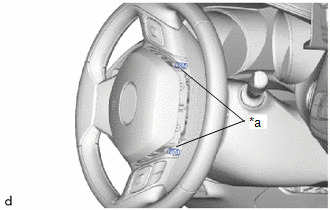
3. REMOVE HORN BUTTON ASSEMBLY
CAUTION:
When storing the horn button assembly, keep the airbag deployment side facing upward.
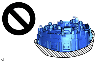
.png) |
Deployment Side |
(a) Check that the ignition switch off.
(b) Check that the cable is disconnected from the negative (-) battery terminal.
CAUTION:
Wait at least 90 seconds after disconnecting the cable from the negative (-) battery terminal to disable the SRS system.
|
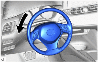
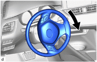
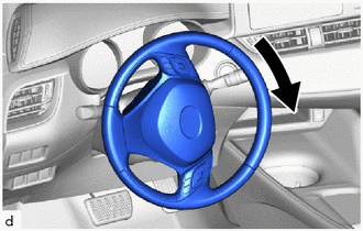
(c) Turn the steering wheel assembly 90° to the left. |
|
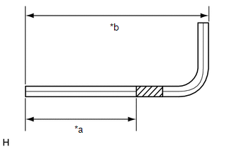
(d) Wrap protective tape around a 6 mm hexagon wrench as shown in the illustration.
|
*a |
55 mm (2.17 in.) |
|
*b |
95 mm (3.74 in.) |
|
|
Protective Tape |
HINT:
Use a 6 mm hexagon wrench with a long arm length of approximately 95 mm (3.74 in.).
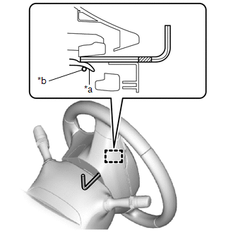
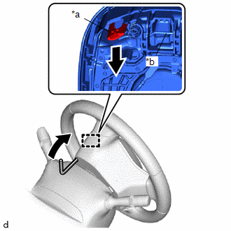
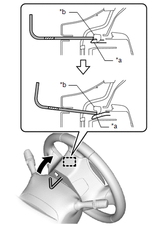
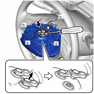
(e) Insert the 6 mm hexagon wrench into the service hole until the protective tape is at the position shown in the illustration.
HINT:
Make sure to insert the 6 mm hexagon wrench into the service hole on the backside of the steering wheel assembly.
|
*a |
Housing Tab |
|
*b |
Omega Spring |
|
|
Protective Tape |
|
(f) Using the 6 mm hexagon wrench, push down the housing tab to disengage the hook as shown in the illustration. HINT: Pushing down the housing tab will push the omega spring and disengage it from the hook. |
|
|
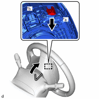
(g) Turn the steering wheel assembly 180° to the right. |
|
(h) Insert the 6 mm hexagon wrench into the service hole until the protective tape is at the position shown in the illustration.
HINT:
Make sure to insert the 6 mm hexagon wrench into the service hole on the backside of the steering wheel assembly.
|
*a |
Housing Tab |
|
*b |
Omega Spring |
|
|
Protective Tape |
|
(i) Using the 6 mm hexagon wrench, push down the housing tab to disengage the hook as shown in the illustration. NOTICE: Lightly hold the horn button assembly so that it does not fall. HINT: Pushing down the housing tab will push the omega spring and disengage it from the hook. |
|
|
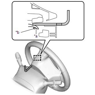
(j) Check that each hook is disengaged. HINT: If a hook is disengaged, the spring will be visible at the location shown in the illustration. |
|
|
(k) Turn the steering wheel assembly 90° to the right. |
|
|
(l) Using a 6 mm hexagon wrench, push the housing tab to disengage the hook as shown in the illustration. NOTICE: Lightly hold the horn button assembly so that it does not fall. HINT:
|
|
(m) Turn the steering wheel assembly 180° to the left to align the front wheels facing straight ahead.
NOTICE:
Do not drop the horn button assembly.
(n) Pull out the horn button assembly from the steering wheel assembly and hold the horn button assembly with one hand.
NOTICE:
When separating the horn button assembly, do not pull the airbag wire harness.
(o) for Single Type:
|
(1) Disconnect the horn connector from the horn button assembly. |
|
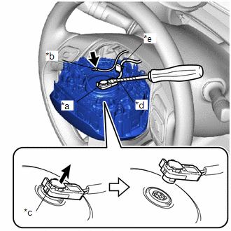
(2) Using a screwdriver with its tip wrapped in protective tape, release the airbag connector lock.
(3) Disconnect the airbag connector.
(4) Disengage the wire harness clamp to remove the horn button assembly
NOTICE:
When disconnecting any airbag connector, take care not to damage the airbag wire harness.
(p) for Dual Type:
|
(1) Disconnect the horn connector from the horn button assembly. |
|
(2) Using a screwdriver with its tip wrapped in protective tape, release the 2 airbag connector locks.
(3) Disconnect the 2 airbag connectors.
(4) Disengage the wire harness clamp to remove the horn button assembly
NOTICE:
When disconnecting any airbag connector, take care not to damage the airbag wire harness.
 On-vehicle Inspection
ON-VEHICLE INSPECTION
CAUTION / NOTICE / HINT
CAUTION:
Be sure to correctly follow the removal and installation procedures for the horn
button assembly.
PROCEDURE
1. INSPECT HORN BUTTON ASSEMBL ...
 Disposal
DISPOSAL
CAUTION / NOTICE / HINT
CAUTION:
Before performing pre-disposal deployment of any SRS part, review and closely
follow all applicable environmental and hazardous material regulations. Pre ...
Other materials:
Toyota CH-R Owners Manual > Before driving: Trailer towing
Toyota does not recommend towing a trailer with your vehicle.
Toyota also does not recommend the installation of a tow hitch or
the use of a tow hitch carrier for a wheelchair, scooter, bicycle, etc. Your vehicle
is not designed for trailer towing or for the use of tow hitch mounted carriers. ...
Toyota CH-R Service Manual > Meter / Gauge System: Fuel Sender Open Detected (B1500)
DESCRIPTION
This DTC is stored when the combination meter assembly detects a fuel sender
gauge assembly malfunction via a direct line.
DTC No.
Detection Item
DTC Detection Condition
Trouble Area
Memory
B1500
Fuel ...
Toyota C-HR (AX20) 2023-2026 Owner's Manual
Toyota CH-R Owners Manual
- For safety and security
- Instrument cluster
- Operation of each component
- Driving
- Interior features
- Maintenance and care
- When trouble arises
- Vehicle specifications
- For owners
Toyota CH-R Service Manual
- Introduction
- Maintenance
- Audio / Video
- Cellular Communication
- Navigation / Multi Info Display
- Park Assist / Monitoring
- Brake (front)
- Brake (rear)
- Brake Control / Dynamic Control Systems
- Brake System (other)
- Parking Brake
- Axle And Differential
- Drive Shaft / Propeller Shaft
- K114 Cvt
- 3zr-fae Battery / Charging
- Networking
- Power Distribution
- Power Assist Systems
- Steering Column
- Steering Gear / Linkage
- Alignment / Handling Diagnosis
- Front Suspension
- Rear Suspension
- Tire / Wheel
- Tire Pressure Monitoring
- Door / Hatch
- Exterior Panels / Trim
- Horn
- Lighting (ext)
- Mirror (ext)
- Window / Glass
- Wiper / Washer
- Door Lock
- Heating / Air Conditioning
- Interior Panels / Trim
- Lighting (int)
- Meter / Gauge / Display
- Mirror (int)
- Power Outlets (int)
- Pre-collision
- Seat
- Seat Belt
- Supplemental Restraint Systems
- Theft Deterrent / Keyless Entry

0.0072