Toyota CH-R Service Manual: Lost communication with Side Airbag Sensor RH (B1622/81,B1623/81,B1632/81,B1633/81,B1642/81,B1643/81,B166D/81,B166E/81)
DESCRIPTION
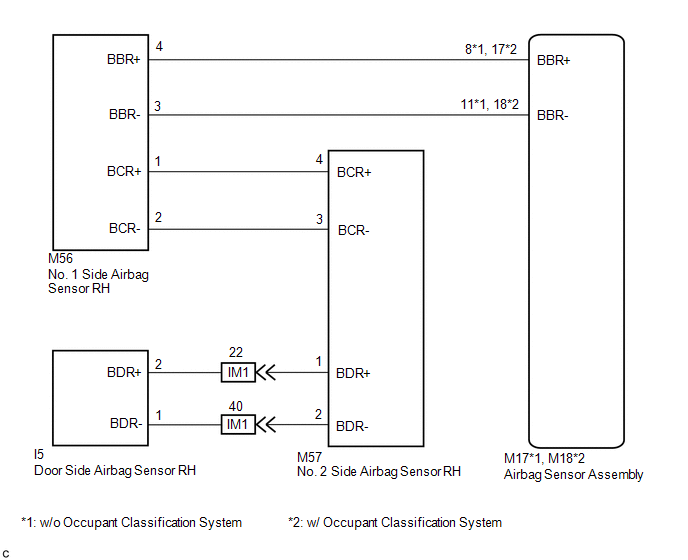
The side collision sensor RH circuit (bus 1) consists of the airbag sensor assembly, door side airbag sensor RH, No. 1 side airbag sensor RH and No. 2 side airbag sensor RH.
The door side airbag sensor RH, No. 1 side airbag sensor RH and No. 2 side airbag sensor RH detect impacts to the vehicle and send signals to the airbag sensor assembly to determine if the airbags and pretensioners should be deployed.
These DTCs are stored when a malfunction is detected in the side collision sensor RH circuit (bus 1).
|
DTC No. |
Detection Item |
DTC Detection Condition |
Trouble Area |
Test Mode / Check Mode |
|---|---|---|---|---|
|
B1622/81 |
Lost communication with Side Airbag Sensor RH |
Any of the following conditions is met:
|
|
Does not apply to test/check mode |
|
B1623/81 |
Side Airbag Sensor Assembly RH Initialization Incomplete |
Any of the following conditions is met:
|
|
Does not apply to test/check mode |
|
B1632/81 |
Lost Communication with Rear Airbag Sensor RH |
Any of the following conditions is met:
|
|
Does not apply to test/check mode |
|
B1633/81 |
Rear Airbag Sensor Assembly RH Initialization Incomplete |
Any of the following conditions is met:
|
|
Does not apply to test/check mode |
|
B1642/81 |
Lost Communication with Side Satellite Sensor Bus RH |
Any of the following conditions is met:
|
|
Does not apply to test/check mode |
|
B1643/81 |
Side Satellite Sensor Bus RH Initialization Incomplete |
Any of the following conditions is met:
|
|
Does not apply to test/check mode |
|
B166D/81 |
Lost Communication with Front Door Pressure Sensor RH |
Any of the following conditions is met:
|
|
Does not apply to test/check mode |
|
B166E/81 |
Front Door Pressure Sensor RH Initialization Incomplete |
Any of the following conditions is met:
|
|
Does not apply to test/check mode |
|
Vehicle Condition |
|||||||||
|---|---|---|---|---|---|---|---|---|---|
|
Pattern 1 |
Pattern 2 |
Pattern 3 |
Pattern 4 |
Pattern 5 |
Pattern 6 |
Pattern 7 |
Pattern 8 |
||
|
Diagnosis Condition |
Ignition switch ON |
○ |
○ |
○ |
○ |
○ |
○ |
○ |
○ |
|
Malfunction Status |
The airbag sensor assembly detects a line short in the side collision sensor RH circuit (bus 1) |
○ |
- |
- |
- |
- |
- |
- |
- |
|
The airbag sensor assembly detects a short to ground in the side collision sensor RH circuit (bus 1) |
- |
○ |
- |
- |
- |
- |
- |
- |
|
|
The airbag sensor assembly detects a short to B+ in the side collision sensor RH circuit (bus 1) |
- |
- |
○ |
- |
- |
- |
- |
- |
|
|
The airbag sensor assembly detects an open in the side collision sensor RH circuit (bus 1) |
- |
- |
- |
○ |
- |
- |
- |
- |
|
|
No. 1 side airbag sensor RH malfunction |
- |
- |
- |
- |
○ |
- |
- |
- |
|
|
No. 2 side airbag sensor RH malfunction |
- |
- |
- |
- |
- |
○ |
- |
- |
|
|
Door side airbag sensor RH malfunction |
- |
- |
- |
- |
- |
- |
○ |
- |
|
|
Airbag sensor assembly malfunction |
- |
- |
- |
- |
- |
- |
- |
○ |
|
|
Detection Time |
- |
- |
- |
- |
- |
- |
- |
- |
|
|
Number of Trips |
1 trip |
1 trip |
1 trip |
1 trip |
1 trip |
1 trip |
1 trip |
1 trip |
|
|
Vehicle Condition |
|||||||||
|---|---|---|---|---|---|---|---|---|---|
|
Pattern 1 |
Pattern 2 |
Pattern 3 |
Pattern 4 |
Pattern 5 |
Pattern 6 |
Pattern 7 |
Pattern 8 |
||
|
Diagnosis Condition |
Ignition switch ON |
○ |
○ |
○ |
○ |
○ |
○ |
○ |
○ |
|
Malfunction Status |
The airbag sensor assembly detects a line short in the side collision sensor RH circuit (bus 1) |
○ |
- |
- |
- |
- |
- |
- |
- |
|
The airbag sensor assembly detects a short to ground in the side collision sensor RH circuit (bus 1) |
- |
○ |
- |
- |
- |
- |
- |
- |
|
|
The airbag sensor assembly detects a short to B+ in the side collision sensor RH circuit (bus 1) |
- |
- |
○ |
- |
- |
- |
- |
- |
|
|
The airbag sensor assembly detects an open in the side collision sensor RH circuit (bus 1) |
- |
- |
- |
○ |
- |
- |
- |
- |
|
|
No. 1 side airbag sensor RH malfunction |
- |
- |
- |
- |
○ |
- |
- |
- |
|
|
No. 2 side airbag sensor RH malfunction |
- |
- |
- |
- |
- |
○ |
- |
- |
|
|
Door side airbag sensor RH malfunction |
- |
- |
- |
- |
- |
- |
○ |
- |
|
|
Airbag sensor assembly malfunction |
- |
- |
- |
- |
- |
- |
- |
○ |
|
|
Detection Time |
- |
- |
- |
- |
- |
- |
- |
- |
|
|
Number of Trips |
1 trip |
1 trip |
1 trip |
1 trip |
1 trip |
1 trip |
1 trip |
1 trip |
|
HINT:
DTC will be output when conditions for either of the patterns in the table above are met.
WIRING DIAGRAM
CAUTION / NOTICE / HINT
NOTICE:
After turning the ignition switch off, waiting time may be required before disconnecting the cable from the negative (-) battery terminal. Therefore, make sure to read the disconnecting the cable from the negative (-) battery terminal notices before proceeding with work.
Click here .gif)
PROCEDURE
|
1. |
CHECK CURRENT DTC |
(a) Check for current DTCs.
Click here
HINT:
- DTCs indicating communication errors will be changed to DTCs indicating errors in initialization by turning the ignition switch off and then ON again.
- Codes other than current DTCs B1622/81, B1623/81, B1632/81, B1633/81, B1642/81, B1643/81, B166D/81 and B166E/81 may be output at this time, but they are not related to this check.
|
Result |
Proceed to |
|---|---|
|
Current DTC B1642/81 or B1643/81 is output. |
A |
|
Current DTC B1623/81 is output. |
B |
|
Current DTC B1633/81 is output. |
C |
|
Current DTC B166D/81 or B166E/81 is output. |
D |
|
Current DTC B1622/81 is output. |
E |
|
Current DTC B1632/81 is output. |
F |
|
Current DTCs B1622/81, B1623/81, B1632/81, B1633/81, B1642/81, B1643/81, B166D/81 and B166E/81 are not output. |
G |
| B | .gif) |
GO TO STEP 22 |
| C | |
GO TO STEP 42 |
| D | |
GO TO STEP 51 |
| E | |
GO TO STEP 62 |
| F | |
GO TO STEP 63 |
| G | |
USE SIMULATION METHOD TO CHECK |
|
.gif)
|
2. |
CHECK CONNECTORS |
(a) Turn the ignition switch off.
(b) Disconnect the cable from the negative (-) battery terminal.
CAUTION:
Wait at least 90 seconds after disconnecting the cable from the negative (-) battery terminal to disable the SRS system.
(c) Check that the connectors are properly connected to the airbag sensor assembly, No. 1 side airbag sensor RH, No. 2 side airbag sensor RH and door side airbag sensor RH. Also check that the connectors that link the floor wire and front door wire RH are properly connected.
OK:
The connectors are properly connected.
HINT:
If the connectors are not properly connected, reconnect the connectors and proceed to the next inspection.
(d) Disconnect the connectors from the airbag sensor assembly, No. 1 side airbag sensor RH, No. 2 side airbag sensor RH and door side airbag sensor RH. Also disconnect the connectors that link the floor wire and front door wire RH.
(e) Check that the terminals of the connectors are not deformed or damaged.
OK:
The terminals are not deformed or damaged.
| NG | |
REPLACE WIRE HARNESS |
|
|
3. |
CHECK FLOOR WIRE (OPEN) |
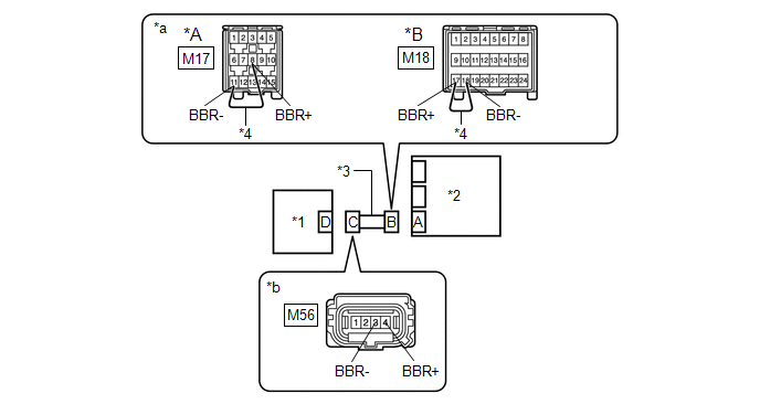
(a) w/o Occupant Classification System
(1) Using a service wire, connect terminals 8 (BBR+) and 11 (BBR-) of connector B.
NOTICE:
Do not forcibly insert the service wire into the terminals of the connector when connecting the wire.
(b) w/ Occupant Classification System
(1) Using a service wire, connect terminals 17 (BBR+) and 18 (BBR-) of connector B.
NOTICE:
Do not forcibly insert the service wire into the terminals of the connector when connecting the wire.
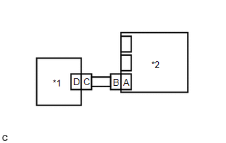
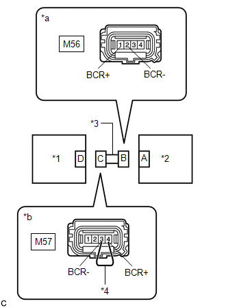
|
*A |
w/o Occupant Classification System |
*B |
w/ Occupant Classification System |
|
*1 |
No. 1 Side Airbag Sensor RH |
*2 |
Airbag Sensor Assembly |
|
*3 |
Floor Wire |
*4 |
Service Wire |
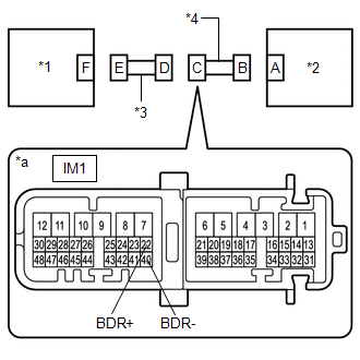
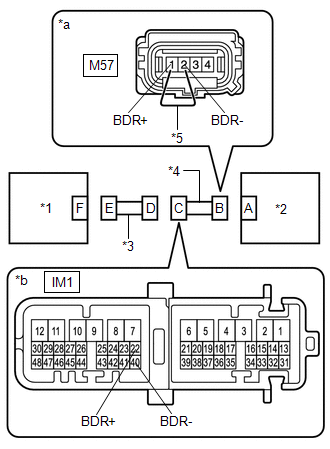
|
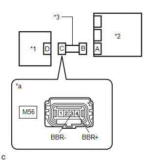
*a |
Front view of wire harness connector (to Airbag Sensor Assembly) |
*b |
Front view of wire harness connector (to No. 1 Side Airbag Sensor RH) |
(c) Measure the resistance according to the value(s) in the table below.
Standard Resistance:
|
Tester Connection |
Condition |
Specified Condition |
|---|---|---|
|
M56-4 (BBR+) - M56-3 (BBR-) |
Always |
Below 1 Ω |
(d) Disconnect the service wire from connector B.
| NG | |
REPLACE FLOOR WIRE |
|
|
4. |
CHECK FLOOR WIRE (SHORT) |
|
(a) Measure the resistance according to the value(s) in the table below. Standard Resistance:
|
|
| NG | |
REPLACE FLOOR WIRE |
|
|
5. |
CHECK FLOOR WIRE (SHORT TO B+) |
|
(a) Connect the cable to the negative (-) battery terminal. |
|
(b) Turn the ignition switch ON.
(c) Measure the voltage according to the value(s) in the table below.
Standard Voltage:
|
Tester Connection |
Switch Condition |
Specified Condition |
|---|---|---|
|
M56-4 (BBR+) - Body ground |
Ignition switch ON |
Below 1 V |
|
M56-3 (BBR-) - Body ground |
Ignition switch ON |
Below 1 V |
(d) Turn the ignition switch off.
(e) Disconnect the cable from the negative (-) battery terminal.
CAUTION:
Wait at least 90 seconds after disconnecting the cable from the negative (-) battery terminal to disable the SRS system.
| NG | |
REPLACE FLOOR WIRE |
|
|
6. |
CHECK FLOOR WIRE (SHORT TO GROUND) |
|
(a) Measure the resistance according to the value(s) in the table below. Standard Resistance:
|
|
| NG | |
REPLACE FLOOR WIRE |
|
|
7. |
CHECK FLOOR WIRE (OPEN) |
|
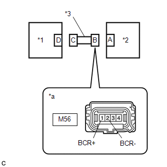
(a) Using a service wire, connect terminals 4 (BCR+) and 3 (BCR-) of connector C. NOTICE: Do not forcibly insert the service wire into the terminals of the connector when connecting the wire. |
|

(b) Measure the resistance according to the value(s) in the table below.
Standard Resistance:
|
Tester Connection |
Condition |
Specified Condition |
|---|---|---|
|
M56-1 (BCR+) - M56-2 (BCR-) |
Always |
Below 1 Ω |
(c) Disconnect the service wire from connector C.
| NG | |
REPLACE FLOOR WIRE |
|
|
8. |
CHECK FLOOR WIRE (SHORT) |
|
(a) Measure the resistance according to the value(s) in the table below. Standard Resistance:
|
|
| NG | |
REPLACE FLOOR WIRE |
|
|
9. |
CHECK FLOOR WIRE (SHORT TO B+) |
|
(a) Connect the cable to the negative (-) battery terminal. |
|
(b) Turn the ignition switch ON.
(c) Measure the voltage according to the value(s) in the table below.
Standard Voltage:
|
Tester Connection |
Switch Condition |
Specified Condition |
|---|---|---|
|
M56-1 (BCR+) - Body ground |
Ignition switch ON |
Below 1 V |
|
M56-2 (BCR-) - Body ground |
Ignition switch ON |
Below 1 V |
(d) Turn the ignition switch off.
(e) Disconnect the cable from the negative (-) battery terminal.
CAUTION:
Wait at least 90 seconds after disconnecting the cable from the negative (-) battery terminal to disable the SRS system.
| NG | |
REPLACE FLOOR WIRE |
|
|
10. |
CHECK FLOOR WIRE (SHORT TO GROUND) |
|
(a) Measure the resistance according to the value(s) in the table below. Standard Resistance:
|
|
| NG | |
REPLACE FLOOR WIRE |
|
|
11. |
CHECK WIRE HARNESS (OPEN) |
|
(a) Connect the connectors that link the floor wire and front door wire RH. |
|

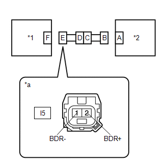
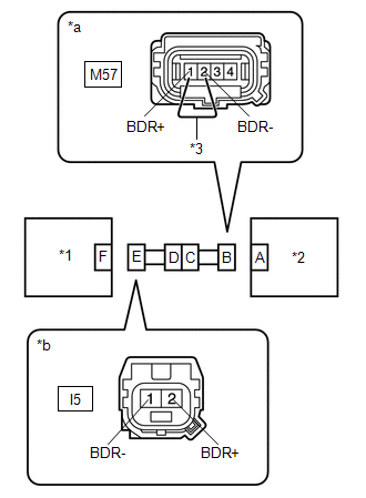
(b) Using a service wire, connect terminals 1 (BDR+) and 2 (BDR-) of connector B.
NOTICE:
Do not forcibly insert the service wire into the terminals of the connector when connecting the wire.
(c) Measure the resistance according to the value(s) in the table below.
Standard Resistance:
|
Tester Connection |
Condition |
Specified Condition |
|---|---|---|
|
I5-2 (BDR+) - I5-1 (BDR-) |
Always |
Below 1 Ω |
| NG | |
GO TO STEP 21 |
|
|
12. |
CHECK WIRE HARNESS (SHORT) |
|
(a) Disconnect the service wire from connector B. |
|
(b) Measure the resistance according to the value(s) in the table below.
Standard Resistance:
|
Tester Connection |
Condition |
Specified Condition |
|---|---|---|
|
I5-2 (BDR+) - I5-1 (BDR-) |
Always |
1 MΩ or higher |
| NG | |
GO TO STEP 20 |
|
|
13. |
CHECK WIRE HARNESS (SHORT TO B+) |
|
(a) Connect the cable to the negative (-) battery terminal. |
|
(b) Turn the ignition switch ON.
(c) Measure the voltage according to the value(s) in the table below.
Standard Voltage:
|
Tester Connection |
Switch Condition |
Specified Condition |
|---|---|---|
|
I5-2 (BDR+) - Body ground |
Ignition switch ON |
Below 1 V |
|
I5-1 (BDR-) - Body ground |
Ignition switch ON |
Below 1 V |
(d) Turn the ignition switch off.
(e) Disconnect the cable from the negative (-) battery terminal.
CAUTION:
Wait at least 90 seconds after disconnecting the cable from the negative (-) battery terminal to disable the SRS system.
| NG | |
GO TO STEP 19 |
|
|
14. |
CHECK WIRE HARNESS (SHORT TO GROUND) |
|
(a) Measure the resistance according to the value(s) in the table below. Standard Resistance:
|
|
| NG | |
GO TO STEP 18 |
|
|
15. |
CHECK NO. 1 SIDE AIRBAG SENSOR RH |
|
(a) Connect the connectors to the No. 2 side airbag sensor RH, door side airbag sensor RH and airbag sensor assembly. |
|
(b) Interchange the No. 1 side airbag sensor RH with LH and connect the connectors.
(c) Connect the cable to the negative (-) battery terminal.
(d) Clear the DTCs stored in memory.
Click here
(e) Turn the ignition switch off.
(f) Turn the ignition switch ON, and wait for at least 60 seconds.
(g) Check for DTCs.
Click here
HINT:
Codes other than DTCs B1642/81, B1643/81, B1647/82 and B1648/82 may be output at this time, but they are not related to this check.
|
Result |
Proceed to |
|---|---|
|
DTC B1642/81 or B1643/81 is output. |
A |
|
DTC B1647/82 or B1648/82 is output. |
B |
|
DTCs B1642/81, B1643/81, B1647/82 and B1648/82 are not output. |
C |
(h) Turn the ignition switch off.
(i) Disconnect the cable from the negative (-) battery terminal.
CAUTION:
Wait at least 90 seconds after disconnecting the cable from the negative (-) battery terminal to disable the SRS system.
(j) Return the No. 1 side airbag sensor RH and LH to their original positions and connect the connectors.
| B | |
REPLACE NO. 1 SIDE AIRBAG SENSOR RH |
| C | |
USE SIMULATION METHOD TO CHECK |
|
|
16. |
CHECK NO. 2 SIDE AIRBAG SENSOR RH |
|
(a) Interchange the No. 2 side airbag sensor RH with LH and connect the connectors. |
|
.png)
(b) Connect the cable to the negative (-) battery terminal.
(c) Clear the DTCs stored in memory.
Click here
(d) Turn the ignition switch off.
(e) Turn the ignition switch ON, and wait for at least 60 seconds.
(f) Check for DTCs.
Click here
HINT:
Codes other than DTCs B1642/81, B1643/81, B1647/82 and B1648/82 may be output at this time, but they are not related to this check.
|
Result |
Proceed to |
|---|---|
|
DTC B1642/81 or B1643/81 is output. |
A |
|
DTC B1647/82 or B1648/82 is output. |
B |
|
DTCs B1642/81, B1643/81, B1647/82 and B1648/82 are not output. |
C |
(g) Turn the ignition switch off.
(h) Disconnect the cable from the negative (-) battery terminal.
CAUTION:
Wait at least 90 seconds after disconnecting the cable from the negative (-) battery terminal to disable the SRS system.
(i) Return the No. 2 side airbag sensor RH and LH to their original positions and connect the connectors.
| B | |
REPLACE NO. 2 SIDE AIRBAG SENSOR RH |
| C | |
USE SIMULATION METHOD TO CHECK |
|
|
17. |
CHECK DOOR SIDE AIRBAG SENSOR RH |
|
(a) Interchange the door side airbag sensor RH with LH and connect the connectors. |
|
.png)
(b) Connect the cable to the negative (-) battery terminal.
(c) Clear the DTCs stored in memory.
Click here
(d) Turn the ignition switch off.
(e) Turn the ignition switch ON, and wait for at least 60 seconds.
(f) Check for DTCs.
Click here
HINT:
Codes other than DTCs B1642/81, B1643/81, B1647/82 and B1648/82 may be output at this time, but they are not related to this check.
|
Result |
Proceed to |
|---|---|
|
DTC B1642/81 or B1643/81 is output. |
A |
|
DTC B1647/82 or B1648/82 is output. |
B |
|
DTCs B1642/81, B1643/81, B1647/82 and B1648/82 are not output. |
C |
(g) Turn the ignition switch off.
(h) Disconnect the cable from the negative (-) battery terminal.
CAUTION:
Wait at least 90 seconds after disconnecting the cable from the negative (-) battery terminal to disable the SRS system.
(i) Return the door side airbag sensor RH and LH to their original positions and connect the connectors.
| A | |
REPLACE AIRBAG SENSOR ASSEMBLY |
| B | |
REPLACE DOOR SIDE AIRBAG SENSOR RH |
| C | |
USE SIMULATION METHOD TO CHECK |
|
18. |
CHECK FLOOR WIRE (SHORT TO GROUND) |
|
(a) Disconnect the floor wire connector from the front door wire RH. |
|
(b) Measure the resistance according to the value(s) in the table below.
Standard Resistance:
|
Tester Connection |
Condition |
Specified Condition |
|---|---|---|
|
IM1-22 (BDR+) - Body ground |
Always |
1 MΩ or higher |
|
IM1-40 (BDR-) - Body ground |
Always |
1 MΩ or higher |
| OK | |
REPLACE FRONT DOOR WIRE RH |
| NG | |
REPLACE FLOOR WIRE |
|
19. |
CHECK FLOOR WIRE (SHORT TO B+) |
|
(a) Disconnect the floor wire connector from the front door wire RH. |
|
(b) Connect the cable to the negative (-) battery terminal.
(c) Turn the ignition switch ON.
(d) Measure the voltage according to the value(s) in the table below.
Standard Voltage:
|
Tester Connection |
Switch Condition |
Specified Condition |
|---|---|---|
|
IM1-22 (BDR+) - Body ground |
Ignition switch ON |
Below 1 V |
|
IM1-40 (BDR-) - Body ground |
Ignition switch ON |
Below 1 V |
| OK | |
REPLACE FRONT DOOR WIRE RH |
| NG | |
REPLACE FLOOR WIRE |
|
20. |
CHECK FLOOR WIRE (SHORT) |
|
(a) Disconnect the floor wire connector from the front door wire RH. |
|
(b) Measure the resistance according to the value(s) in the table below.
Standard Resistance:
|
Tester Connection |
Condition |
Specified Condition |
|---|---|---|
|
IM1-22 (BDR+) - IM1-40 (BDR-) |
Always |
1 MΩ or higher |
| OK | |
REPLACE FRONT DOOR WIRE RH |
| NG | |
REPLACE FLOOR WIRE |
|
21. |
CHECK FLOOR WIRE (OPEN) |
|
(a) Disconnect the floor wire connector from the front door wire RH. HINT: The service wire has already been inserted into connector B. |
|
(b) Measure the resistance according to the value(s) in the table below.
Standard Resistance:
|
Tester Connection |
Condition |
Specified Condition |
|---|---|---|
|
IM1-22 (BDR+) - IM1-40 (BDR-) |
Always |
Below 1 Ω |
(c) Disconnect the service wire from connector B.
| OK | |
REPLACE FRONT DOOR WIRE RH |
| NG | |
REPLACE FLOOR WIRE |
|
22. |
CHECK HISTORY DTC |
(a) Check for history DTCs.
Click here
HINT:
Codes other than history DTC B1622/81 may be output at this time, but they are not related to this check.
|
Result |
Proceed to |
|---|---|
|
History DTC B1622/81 is not output. |
A |
|
History DTC B1622/81 is output. |
B |
| B | |
GO TO STEP 41 |
|
|
23. |
CHECK CONNECTORS |
(a) Turn the ignition switch off.
(b) Disconnect the cable from the negative (-) battery terminal.
CAUTION:
Wait at least 90 seconds after disconnecting the cable from the negative (-) battery terminal to disable the SRS system.
(c) Check that the connectors are properly connected to the airbag sensor assembly, No. 1 side airbag sensor RH, No. 2 side airbag sensor RH and door side airbag sensor RH. Also check that the connectors that link the floor wire and front door wire RH are properly connected.
OK:
The connectors are properly connected.
HINT:
If the connectors are not properly connected, reconnect the connectors and proceed to the next inspection.
(d) Disconnect the connectors from the airbag sensor assembly, No. 1 side airbag sensor RH, No. 2 side airbag sensor RH and door side airbag sensor RH. Also disconnect the connectors that link the floor wire and front door wire RH.
(e) Check that the terminals of the connectors are not deformed or damaged.
OK:
The terminals are not deformed or damaged.
| NG | |
REPLACE WIRE HARNESS |
|
|
24. |
CHECK FLOOR WIRE (OPEN) |
(a) w/o Occupant Classification System
(1) Using a service wire, connect terminals 8 (BBR+) and 11 (BBR-) of connector B.
NOTICE:
Do not forcibly insert the service wire into the terminals of the connector when connecting the wire.
(b) w/ Occupant Classification System
(1) Using a service wire, connect terminals 17 (BBR+) and 18 (BBR-) of connector B.
NOTICE:
Do not forcibly insert the service wire into the terminals of the connector when connecting the wire.

|
*A |
w/o Occupant Classification System |
*B |
w/ Occupant Classification System |
|
*1 |
No. 1 Side Airbag Sensor RH |
*2 |
Airbag Sensor Assembly |
|
*3 |
Floor Wire |
*4 |
Service Wire |
|
*a |
Front view of wire harness connector (to Airbag Sensor Assembly) |
*b |
Front view of wire harness connector (to No. 1 Side Airbag Sensor RH) |
(c) w/ Occupant Classification System
(1) Using a service wire, connect terminals 17 (BBR+) and 18 (BBR-) of connector B.
NOTICE:
Do not forcibly insert the service wire into the terminals of the connector when connecting the wire.
(d) Measure the resistance according to the value(s) in the table below.
Standard Resistance:
|
Tester Connection |
Condition |
Specified Condition |
|---|---|---|
|
M56-4 (BBR+) - M56-3 (BBR-) |
Always |
Below 1 Ω |
(e) Disconnect the service wire from connector B.
| NG | |
REPLACE FLOOR WIRE |
|
|
25. |
CHECK FLOOR WIRE (SHORT) |
|
(a) Measure the resistance according to the value(s) in the table below. Standard Resistance:
|
|

| NG | |
REPLACE FLOOR WIRE |
|
|
26. |
CHECK FLOOR WIRE (SHORT TO B+) |
|
(a) Connect the cable to the negative (-) battery terminal. |
|
(b) Turn the ignition switch ON.
(c) Measure the voltage according to the value(s) in the table below.
Standard Voltage:
|
Tester Connection |
Switch Condition |
Specified Condition |
|---|---|---|
|
M56-4 (BBR+) - Body ground |
Ignition switch ON |
Below 1 V |
|
M56-3 (BBR-) - Body ground |
Ignition switch ON |
Below 1 V |
(d) Turn the ignition switch off.
(e) Disconnect the cable from the negative (-) battery terminal.
CAUTION:
Wait at least 90 seconds after disconnecting the cable from the negative (-) battery terminal to disable the SRS system.
| NG | |
REPLACE FLOOR WIRE |
|
|
27. |
CHECK FLOOR WIRE (SHORT TO GROUND) |
|
(a) Measure the resistance according to the value(s) in the table below. Standard Resistance:
|
|
| NG | |
REPLACE FLOOR WIRE |
|
|
28. |
CHECK FLOOR WIRE (OPEN) |
|
(a) Using a service wire, connect terminals 4 (BCR+) and 3 (BCR-) of connector C. NOTICE: Do not forcibly insert the service wire into the terminals of the connector when connecting the wire. |
|
(b) Measure the resistance according to the value(s) in the table below.
Standard Resistance:
|
Tester Connection |
Condition |
Specified Condition |
|---|---|---|
|
M56-1 (BCR+) - M56-2 (BCR-) |
Always |
Below 1 Ω |
(c) Disconnect the service wire from connector C.
| NG | |
REPLACE FLOOR WIRE |
|
|
29. |
CHECK FLOOR WIRE (SHORT) |
|
(a) Measure the resistance according to the value(s) in the table below. Standard Resistance:
|
|
| NG | |
REPLACE FLOOR WIRE |
|
|
30. |
CHECK FLOOR WIRE (SHORT TO B+) |
|
(a) Connect the cable to the negative (-) battery terminal. |
|
(b) Turn the ignition switch ON.
(c) Measure the voltage according to the value(s) in the table below.
Standard Voltage:
|
Tester Connection |
Switch Condition |
Specified Condition |
|---|---|---|
|
M56-1 (BCR+) - Body ground |
Ignition switch ON |
Below 1 V |
|
M56-2 (BCR-) - Body ground |
Ignition switch ON |
Below 1 V |
(d) Turn the ignition switch off.
(e) Disconnect the cable from the negative (-) battery terminal.
CAUTION:
Wait at least 90 seconds after disconnecting the cable from the negative (-) battery terminal to disable the SRS system.
| NG | |
REPLACE FLOOR WIRE |
|
|
31. |
CHECK FLOOR WIRE (SHORT TO GROUND) |
|
(a) Measure the resistance according to the value(s) in the table below. Standard Resistance:
|
|
| NG | |
REPLACE FLOOR WIRE |
|
|
32. |
CHECK WIRE HARNESS (OPEN) |
|
(a) Connect the connectors that link the floor wire and front door wire RH. |
|
(b) Using a service wire, connect terminals 1 (BDR+) and 2 (BDR-) of connector B.
NOTICE:
Do not forcibly insert the service wire into the terminals of the connector when connecting the wire.
(c) Measure the resistance according to the value(s) in the table below.
Standard Resistance:
|
Tester Connection |
Condition |
Specified Condition |
|---|---|---|
|
I5-2 (BDR+) - I5-1 (BDR-) |
Always |
Below 1 Ω |
| NG | |
GO TO STEP 40 |
|
|
33. |
CHECK WIRE HARNESS (SHORT) |
|
(a) Disconnect the service wire from connector B. |
|
(b) Measure the resistance according to the value(s) in the table below.
Standard Resistance:
|
Tester Connection |
Condition |
Specified Condition |
|---|---|---|
|
I5-2 (BDR+) - I5-1 (BDR-) |
Always |
1 MΩ or higher |
| NG | |
GO TO STEP 39 |
|
|
34. |
CHECK WIRE HARNESS (SHORT TO B+) |
|
(a) Connect the cable to the negative (-) battery terminal. |
|
(b) Turn the ignition switch ON.
(c) Measure the voltage according to the value(s) in the table below.
Standard Voltage:
|
Tester Connection |
Switch Condition |
Specified Condition |
|---|---|---|
|
I5-2 (BDR+) - Body ground |
Ignition switch ON |
Below 1 V |
|
I5-1 (BDR-) - Body ground |
Ignition switch ON |
Below 1 V |
(d) Turn the ignition switch off.
(e) Disconnect the cable from the negative (-) battery terminal.
CAUTION:
Wait at least 90 seconds after disconnecting the cable from the negative (-) battery terminal to disable the SRS system.
| NG | |
GO TO STEP 38 |
|
|
35. |
CHECK WIRE HARNESS (SHORT TO GROUND) |
|
(a) Measure the resistance according to the value(s) in the table below. Standard Resistance:
|
|
| NG | |
GO TO STEP 37 |
|
|
36. |
CHECK NO. 1 SIDE AIRBAG SENSOR RH |
|
(a) Connect the connectors to the No. 2 side airbag sensor RH, door side airbag sensor RH and airbag sensor assembly. |
|
(b) Interchange the No. 1 side airbag sensor RH with LH and connect the connectors.
(c) Connect the cable to the negative (-) battery terminal.
(d) Clear the DTCs stored in memory.
Click here
(e) Turn the ignition switch off.
(f) Turn the ignition switch ON, and wait for at least 60 seconds.
(g) Check for DTCs.
Click here
HINT:
Codes other than DTCs B1623/81 and B1628/82 may be output at this time, but they are not related to this check.
|
Result |
Proceed to |
|---|---|
|
DTC B1623/81 is output. |
A |
|
DTC B1628/82 is output. |
B |
|
DTCs B1623/81 and B1628/82 are not output. |
C |
(h) Turn the ignition switch off.
(i) Disconnect the cable from the negative (-) battery terminal.
CAUTION:
Wait at least 90 seconds after disconnecting the cable from the negative (-) battery terminal to disable the SRS system.
(j) Return the No. 1 side airbag sensor RH and LH to their original positions and connect the connectors.
| A | |
REPLACE AIRBAG SENSOR ASSEMBLY |
| B | |
REPLACE NO. 1 SIDE AIRBAG SENSOR RH |
| C | |
USE SIMULATION METHOD TO CHECK |
|
37. |
CHECK FLOOR WIRE (SHORT TO GROUND) |
|
(a) Disconnect the floor wire connector from the front door wire RH. |
|
(b) Measure the resistance according to the value(s) in the table below.
Standard Resistance:
|
Tester Connection |
Condition |
Specified Condition |
|---|---|---|
|
IM1-22 (BDR+) - Body ground |
Always |
1 MΩ or higher |
|
IM1-40 (BDR-) - Body ground |
Always |
1 MΩ or higher |
| OK | |
REPLACE FRONT DOOR WIRE RH |
| NG | |
REPLACE FLOOR WIRE |
|
38. |
CHECK FLOOR WIRE (SHORT TO B+) |
|
(a) Disconnect the floor wire connector from the front door wire RH. |
|
(b) Connect the cable to the negative (-) battery terminal.
(c) Turn the ignition switch ON.
(d) Measure the voltage according to the value(s) in the table below.
Standard Voltage:
|
Tester Connection |
Switch Condition |
Specified Condition |
|---|---|---|
|
IM1-22 (BDR+) - Body ground |
Ignition switch ON |
Below 1 V |
|
IM1-40 (BDR-) - Body ground |
Ignition switch ON |
Below 1 V |
| OK | |
REPLACE FRONT DOOR WIRE RH |
| NG | |
REPLACE FLOOR WIRE |
|
39. |
CHECK FLOOR WIRE (SHORT) |
|
(a) Disconnect the floor wire connector from the front door wire RH. |
|
(b) Measure the resistance according to the value(s) in the table below.
Standard Resistance:
|
Tester Connection |
Condition |
Specified Condition |
|---|---|---|
|
IM1-22 (BDR+) - IM1-40 (BDR-) |
Always |
1 MΩ or higher |
| OK | |
REPLACE FRONT DOOR WIRE RH |
| NG | |
REPLACE FLOOR WIRE |
|
40. |
CHECK FLOOR WIRE (OPEN) |
|
(a) Disconnect the floor wire connector from the front door wire RH. HINT: The service wire has already been inserted into connector B. |
|
(b) Measure the resistance according to the value(s) in the table below.
Standard Resistance:
|
Tester Connection |
Condition |
Specified Condition |
|---|---|---|
|
IM1-22 (BDR+) - IM1-40 (BDR-) |
Always |
Below 1 Ω |
(c) Disconnect the service wire from connector B.
| OK | |
REPLACE FRONT DOOR WIRE RH |
| NG | |
REPLACE FLOOR WIRE |
|
41. |
CHECK NO. 1 SIDE AIRBAG SENSOR RH |
|
(a) Turn the ignition switch off. |
|
(b) Disconnect the cable from the negative (-) battery terminal.
CAUTION:
Wait at least 90 seconds after disconnecting the cable from the negative (-) battery terminal to disable the SRS system.
(c) Interchange the No. 1 side airbag sensor RH with LH and connect the connectors.
(d) Connect the cable to the negative (-) battery terminal.
(e) Clear the DTCs stored in memory.
Click here
(f) Turn the ignition switch off.
(g) Turn the ignition switch ON, and wait for at least 60 seconds.
(h) Check for DTCs.
Click here
HINT:
Codes other than DTCs B1622/81 and B1627/82 may be output at this time, but they are not related to this check.
|
Result |
Proceed to |
|---|---|
|
DTC B1622/81 is output. |
A |
|
DTC B1627/82 is output. |
B |
|
DTCs B1622/81 and B1627/82 are not output. |
C |
(i) Turn the ignition switch off.
(j) Disconnect the cable from the negative (-) battery terminal.
CAUTION:
Wait at least 90 seconds after disconnecting the cable from the negative (-) battery terminal to disable the SRS system.
(k) Return the No. 1 side airbag sensor RH and LH to their original positions and connect the connectors.
| A | |
REPLACE AIRBAG SENSOR ASSEMBLY |
| B | |
REPLACE NO. 1 SIDE AIRBAG SENSOR RH |
| C | |
USE SIMULATION METHOD TO CHECK |
|
42. |
CHECK HISTORY DTC |
(a) Check for history DTCs.
Click here
HINT:
Codes other than history DTC B1632/81 may be output at this time, but they are not related to this check.
|
Result |
Proceed to |
|---|---|
|
History DTC B1632/81 is not output. |
A |
|
History DTC B1632/81 is output. |
B |
| B | |
GO TO STEP 50 |
|
|
43. |
CHECK CONNECTORS |
(a) Turn the ignition switch off.
(b) Disconnect the cable from the negative (-) battery terminal.
CAUTION:
Wait at least 90 seconds after disconnecting the cable from the negative (-) battery terminal to disable the SRS system.
(c) Check that the connectors are properly connected to the No. 1 side airbag sensor RH and No. 2 side airbag sensor RH.
OK:
The connectors are properly connected.
HINT:
If the connectors are not properly connected, reconnect the connectors and proceed to the next inspection.
(d) Disconnect the connectors from the No. 1 side airbag sensor RH and No. 2 side airbag sensor RH.
(e) Check that the terminals of the connectors are not deformed or damaged.
OK:
The terminals are not deformed or damaged.
| NG | |
REPLACE FLOOR WIRE |
|
|
44. |
CHECK FLOOR WIRE (OPEN) |
|
(a) Using a service wire, connect terminals 4 (BCR+) and 3 (BCR-) of connector C. NOTICE: Do not forcibly insert the service wire into the terminals of the connector when connecting the wire. |
|
(b) Measure the resistance according to the value(s) in the table below.
Standard Resistance:
|
Tester Connection |
Condition |
Specified Condition |
|---|---|---|
|
M56-1 (BCR+) - M56-2 (BCR-) |
Always |
Below 1 Ω |
(c) Disconnect the service wire from connector C.
| NG | |
REPLACE FLOOR WIRE |
|
|
45. |
CHECK FLOOR WIRE (SHORT) |
|
(a) Measure the resistance according to the value(s) in the table below. Standard Resistance:
|
|
| NG | |
REPLACE FLOOR WIRE |
|
|
46. |
CHECK FLOOR WIRE (SHORT TO B+) |
|
(a) Connect the cable to the negative (-) battery terminal. |
|
(b) Turn the ignition switch ON.
(c) Measure the voltage according to the value(s) in the table below.
Standard Voltage:
|
Tester Connection |
Switch Condition |
Specified Condition |
|---|---|---|
|
M56-1 (BCR+) - Body ground |
Ignition switch ON |
Below 1 V |
|
M56-2 (BCR-) - Body ground |
Ignition switch ON |
Below 1 V |
(d) Turn the ignition switch off.
(e) Disconnect the cable from the negative (-) battery terminal.
CAUTION:
Wait at least 90 seconds after disconnecting the cable from the negative (-) battery terminal to disable the SRS system.
| NG | |
REPLACE FLOOR WIRE |
|
|
47. |
CHECK FLOOR WIRE (SHORT TO GROUND) |
|
(a) Measure the resistance according to the value(s) in the table below. Standard Resistance:
|
|
| NG | |
REPLACE FLOOR WIRE |
|
|
48. |
CHECK NO. 1 SIDE AIRBAG SENSOR RH |
|
(a) Connect the connector to the No. 2 side airbag sensor RH. |
|
(b) Interchange the No. 1 side airbag sensor RH with LH and connect the connectors.
(c) Connect the cable to the negative (-) battery terminal.
(d) Clear the DTCs stored in memory.
Click here
(e) Turn the ignition switch off.
(f) Turn the ignition switch ON, and wait for at least 60 seconds.
(g) Check for DTCs.
Click here
HINT:
Codes other than DTCs B1633/81 and B1638/82 may be output at this time, but they are not related to this check.
|
Result |
Proceed to |
|---|---|
|
DTC B1633/81 is output. |
A |
|
DTC B1638/82 is output. |
B |
|
DTCs B1633/81 and B1638/82 are not output. |
C |
(h) Turn the ignition switch off.
(i) Disconnect the cable from the negative (-) battery terminal.
CAUTION:
Wait at least 90 seconds after disconnecting the cable from the negative (-) battery terminal to disable the SRS system.
(j) Return the No. 1 side airbag sensor RH and LH to their original positions and connect the connectors.
| B | |
REPLACE NO. 1 SIDE AIRBAG SENSOR RH |
| C | |
USE SIMULATION METHOD TO CHECK |
|
|
49. |
CHECK NO. 2 SIDE AIRBAG SENSOR RH |
|
(a) Interchange the No. 2 side airbag sensor RH with LH and connect the connectors. |
|
(b) Connect the cable to the negative (-) battery terminal.
(c) Clear the DTCs stored in memory.
Click here
(d) Turn the ignition switch off.
(e) Turn the ignition switch ON, and wait for at least 60 seconds.
(f) Check for DTCs.
Click here
HINT:
Codes other than DTCs B1633/81 and B1638/82 may be output at this time, but they are not related to this check.
|
Result |
Proceed to |
|---|---|
|
DTC B1633/81 is output. |
A |
|
DTC B1638/82 is output. |
B |
|
DTCs B1633/81 and B1638/82 are not output. |
C |
(g) Turn the ignition switch off.
(h) Disconnect the cable from the negative (-) battery terminal.
CAUTION:
Wait at least 90 seconds after disconnecting the cable from the negative (-) battery terminal to disable the SRS system.
(i) Return the No. 2 side airbag sensor RH and LH to their original positions and connect the connectors.
| A | |
REPLACE AIRBAG SENSOR ASSEMBLY |
| B | |
REPLACE NO. 2 SIDE AIRBAG SENSOR RH |
| C | |
USE SIMULATION METHOD TO CHECK |
|
50. |
CHECK NO. 2 SIDE AIRBAG SENSOR RH |
|
(a) Turn the ignition switch off. |
|
(b) Disconnect the cable from the negative (-) battery terminal.
CAUTION:
Wait at least 90 seconds after disconnecting the cable from the negative (-) battery terminal to disable the SRS system.
(c) Interchange the No. 2 side airbag sensor RH with LH and connect the connectors.
(d) Connect the cable to the negative (-) battery terminal.
(e) Clear the DTCs stored in memory.
Click here
(f) Turn the ignition switch off.
(g) Turn the ignition switch ON, and wait for at least 60 seconds.
(h) Check for DTCs.
Click here
HINT:
Codes other than DTCs B1632/81 and B1637/82 may be output at this time, but they are not related to this check.
|
Result |
Proceed to |
|---|---|
|
DTC B1632/81 is output. |
A |
|
DTC B1637/82 is output. |
B |
|
DTCs B1632/81 and B1637/82 are not output. |
C |
(i) Turn the ignition switch off.
(j) Disconnect the cable from the negative (-) battery terminal.
CAUTION:
Wait at least 90 seconds after disconnecting the cable from the negative (-) battery terminal to disable the SRS system.
(k) Return the No. 2 side airbag sensor RH and LH to their original positions and connect the connectors.
| A | |
REPLACE AIRBAG SENSOR ASSEMBLY |
| B | |
REPLACE NO. 2 SIDE AIRBAG SENSOR RH |
| C | |
USE SIMULATION METHOD TO CHECK |
|
51. |
CHECK CONNECTORS |
(a) Turn the ignition switch off.
(b) Disconnect the cable from the negative (-) battery terminal.
CAUTION:
Wait at least 90 seconds after disconnecting the cable from the negative (-) battery terminal to disable the SRS system.
(c) Check that the connectors are properly connected to the No. 2 side airbag sensor RH and door side airbag sensor RH. Also check that the connectors that link the floor wire and front door wire RH are properly connected.
OK:
The connectors are properly connected.
HINT:
If the connectors are not properly connected, reconnect the connectors and proceed to the next inspection.
(d) Disconnect the connectors from the No. 2 side airbag sensor RH and door side airbag sensor RH. Also disconnect the connectors that link the floor wire and front door wire RH.
(e) Check that the terminals of the connectors are not deformed or damaged.
OK:
The terminals are not deformed or damaged.
| NG | |
REPLACE WIRE HARNESS |
|
|
52. |
CHECK WIRE HARNESS (OPEN) |
|
(a) Connect the connectors that link the floor wire and front door wire RH. |
|
(b) Using a service wire, connect terminals 1 (BDR+) and 2 (BDR-) of connector B.
NOTICE:
Do not forcibly insert the service wire into the terminals of the connector when connecting the wire.
(c) Measure the resistance according to the value(s) in the table below.
Standard Resistance:
|
Tester Connection |
Condition |
Specified Condition |
|---|---|---|
|
I5-2 (BDR+) - I5-1 (BDR-) |
Always |
Below 1 Ω |
| NG | |
GO TO STEP 61 |
|
|
53. |
CHECK WIRE HARNESS (SHORT) |
|
(a) Disconnect the service wire from connector B. |
|
(b) Measure the resistance according to the value(s) in the table below.
Standard Resistance:
|
Tester Connection |
Condition |
Specified Condition |
|---|---|---|
|
I5-2 (BDR+) - I5-1 (BDR-) |
Always |
1 MΩ or higher |
| NG | |
GO TO STEP 60 |
|
|
54. |
CHECK WIRE HARNESS (SHORT TO B+) |
|
(a) Connect the cable to the negative (-) battery terminal. |
|
(b) Turn the ignition switch ON.
(c) Measure the voltage according to the value(s) in the table below.
Standard Voltage:
|
Tester Connection |
Switch Condition |
Specified Condition |
|---|---|---|
|
I5-2 (BDR+) - Body ground |
Ignition switch ON |
Below 1 V |
|
I5-1 (BDR-) - Body ground |
Ignition switch ON |
Below 1 V |
(d) Turn the ignition switch off.
(e) Disconnect the cable from the negative (-) battery terminal.
CAUTION:
Wait at least 90 seconds after disconnecting the cable from the negative (-) battery terminal to disable the SRS system.
| NG | |
GO TO STEP 59 |
|
|
55. |
CHECK WIRE HARNESS (SHORT TO GROUND) |
|
(a) Measure the resistance according to the value(s) in the table below. Standard Resistance:
|
|
| NG | |
GO TO STEP 58 |
|
|
56. |
CHECK NO. 2 SIDE AIRBAG SENSOR RH |
|
(a) Connect the connector to the door side airbag sensor RH. |
|
(b) Interchange the No. 2 side airbag sensor RH with LH and connect the connectors.
(c) Connect the cable to the negative (-) battery terminal.
(d) Clear the DTCs stored in memory.
Click here
(e) Turn the ignition switch off.
(f) Turn the ignition switch ON, and wait for at least 60 seconds.
(g) Check for DTCs.
Click here
HINT:
Codes other than DTCs B166D/81, B166E/81,B167B/82 and B167C/82 may be output at this time, but they are not related to this check.
|
Result |
Proceed to |
|---|---|
|
DTC B166D/81 or B166E/81 is output. |
A |
|
DTC B167B/82 or B167C/82 is output. |
B |
|
DTCs B166D/81, B166E/81,B167B/82 and B167C/82 are not output. |
C |
(h) Turn the ignition switch off.
(i) Disconnect the cable from the negative (-) battery terminal.
CAUTION:
Wait at least 90 seconds after disconnecting the cable from the negative (-) battery terminal to disable the SRS system.
(j) Return the No. 2 side airbag sensor RH and LH to their original positions and connect the connectors.
| B | |
REPLACE NO. 2 SIDE AIRBAG SENSOR RH |
| C | |
USE SIMULATION METHOD TO CHECK |
|
|
57. |
CHECK DOOR SIDE AIRBAG SENSOR RH |
|
(a) Interchange the door side airbag sensor RH with LH and connect the connectors. |
|
(b) Connect the cable to the negative (-) battery terminal.
(c) Clear the DTCs stored in memory.
Click here
(d) Turn the ignition switch off.
(e) Turn the ignition switch ON, and wait for at least 60 seconds.
(f) Check for DTCs.
Click here
HINT:
Codes other than DTCs B166D/81, B166E/81,B167B/82 and B167C/82 may be output at this time, but they are not related to this check.
|
Result |
Proceed to |
|---|---|
|
DTC B166D/81 or B166E/81 is output. |
A |
|
DTC B167B/82 or B167C/82 is output. |
B |
|
DTCs B166D/81, B166E/81,B167B/82 and B167C/82 are not output. |
C |
(g) Turn the ignition switch off.
(h) Disconnect the cable from the negative (-) battery terminal.
CAUTION:
Wait at least 90 seconds after disconnecting the cable from the negative (-) battery terminal to disable the SRS system.
(i) Return the door side airbag sensor RH and LH to their original positions and connect the connectors.
| A | |
REPLACE AIRBAG SENSOR ASSEMBLY |
| B | |
REPLACE DOOR SIDE AIRBAG SENSOR RH |
| C | |
USE SIMULATION METHOD TO CHECK |
|
58. |
CHECK FLOOR WIRE (SHORT TO GROUND) |
|
(a) Disconnect the floor wire connector from the front door wire RH. |
|
(b) Measure the resistance according to the value(s) in the table below.
Standard Resistance:
|
Tester Connection |
Condition |
Specified Condition |
|---|---|---|
|
IM1-22 (BDR+) - Body ground |
Always |
1 MΩ or higher |
|
IM1-40 (BDR-) - Body ground |
Always |
1 MΩ or higher |
| OK | |
REPLACE FRONT DOOR WIRE RH |
| NG | |
REPLACE FLOOR WIRE |
|
59. |
CHECK FLOOR WIRE (SHORT TO B+) |
|
(a) Disconnect the floor wire connector from the front door wire RH. |
|
(b) Connect the cable to the negative (-) battery terminal.
(c) Turn the ignition switch ON.
(d) Measure the voltage according to the value(s) in the table below.
Standard Voltage:
|
Tester Connection |
Switch Condition |
Specified Condition |
|---|---|---|
|
IM1-22 (BDR+) - Body ground |
Ignition switch ON |
Below 1 V |
|
IM1-40 (BDR-) - Body ground |
Ignition switch ON |
Below 1 V |
| OK | |
REPLACE FRONT DOOR WIRE RH |
| NG | |
REPLACE FLOOR WIRE |
|
60. |
CHECK FLOOR WIRE (SHORT) |
|
(a) Disconnect the floor wire connector from the front door wire RH. |
|
(b) Measure the resistance according to the value(s) in the table below.
Standard Resistance:
|
Tester Connection |
Condition |
Specified Condition |
|---|---|---|
|
IM1-22 (BDR+) - IM1-40 (BDR-) |
Always |
1 MΩ or higher |
| OK | |
REPLACE FRONT DOOR WIRE RH |
| NG | |
REPLACE FLOOR WIRE |
|
61. |
CHECK FLOOR WIRE (OPEN) |
|
(a) Disconnect the floor wire connector from the front door wire RH. HINT: The service wire has already been inserted into connector B. |
|
(b) Measure the resistance according to the value(s) in the table below.
Standard Resistance:
|
Tester Connection |
Condition |
Specified Condition |
|---|---|---|
|
IM1-22 (BDR+) - IM1-40 (BDR-) |
Always |
Below 1 Ω |
(c) Disconnect the service wire from connector B.
| OK | |
REPLACE FRONT DOOR WIRE RH |
| NG | |
REPLACE FLOOR WIRE |
|
62. |
CHECK NO. 1 SIDE AIRBAG SENSOR RH |
|
(a) Turn the ignition switch off. |
|
(b) Disconnect the cable from the negative (-) battery terminal.
CAUTION:
Wait at least 90 seconds after disconnecting the cable from the negative (-) battery terminal to disable the SRS system.
(c) Interchange the No. 1 side airbag sensor RH with LH and connect the connectors.
(d) Connect the cable to the negative (-) battery terminal.
(e) Clear the DTCs stored in memory.
Click here
(f) Turn the ignition switch off.
(g) Turn the ignition switch ON, and wait for at least 60 seconds.
(h) Check for DTCs.
Click here
HINT:
Codes other than DTCs B1622/81 and B1627/82 may be output at this time, but they are not related to this check.
|
Result |
Proceed to |
|---|---|
|
DTC B1622/81 is output. |
A |
|
DTC B1627/82 is output. |
B |
|
DTCs B1622/81 and B1627/82 are not output. |
C |
(i) Turn the ignition switch off.
(j) Disconnect the cable from the negative (-) battery terminal.
CAUTION:
Wait at least 90 seconds after disconnecting the cable from the negative (-) battery terminal to disable the SRS system.
(k) Return the No. 1 side airbag sensor RH and LH to their original positions and connect the connectors.
| A | |
REPLACE AIRBAG SENSOR ASSEMBLY |
| B | |
REPLACE NO. 1 SIDE AIRBAG SENSOR RH |
| C | |
USE SIMULATION METHOD TO CHECK |
|
63. |
CHECK NO. 2 SIDE AIRBAG SENSOR RH |
|
(a) Turn the ignition switch off. |
|
(b) Disconnect the cable from the negative (-) battery terminal.
CAUTION:
Wait at least 90 seconds after disconnecting the cable from the negative (-) battery terminal to disable the SRS system.
(c) Interchange the No. 2 side airbag sensor RH with LH and connect the connectors.
(d) Connect the cable to the negative (-) battery terminal.
(e) Clear the DTCs stored in memory.
Click here
(f) Turn the ignition switch off.
(g) Turn the ignition switch ON, and wait for at least 60 seconds.
(h) Check for DTCs.
Click here
HINT:
Codes other than DTCs B1632/81 and B1637/82 may be output at this time, but they are not related to this check.
|
Result |
Proceed to |
|---|---|
|
DTC B1632/81 is output. |
A |
|
DTC B1637/82 is output. |
B |
|
DTCs B1632/81 and B1637/82 are not output. |
C |
(i) Turn the ignition switch off.
(j) Disconnect the cable from the negative (-) battery terminal.
CAUTION:
Wait at least 90 seconds after disconnecting the cable from the negative (-) battery terminal to disable the SRS system.
(k) Return the No. 2 side airbag sensor RH and LH to their original positions and connect the connectors.
| A | |
REPLACE AIRBAG SENSOR ASSEMBLY |
| B | |
REPLACE NO. 2 SIDE AIRBAG SENSOR RH |
| C | |
USE SIMULATION METHOD TO CHECK |
 Lost Communication with Front Airbag Sensor LH (B1617/84,B1618/84)
DESCRIPTION
The front airbag sensor LH circuit consists of the airbag sensor assembly and
front airbag sensor LH.
The front airbag sensor LH detects impacts to the vehicle and sends signals to
t ...
 Side Airbag Sensor LH Circuit Malfunction (B1625/22)
DESCRIPTION
The side collision sensor LH circuit (bus 1) consists of the airbag sensor assembly,
door side airbag sensor LH, No. 1 side airbag sensor LH and No. 2 side airbag sensor
LH.
The door ...
Other materials:
Toyota CH-R Service Manual > Air Conditioning System(for Automatic Air Conditioning System With Top-mounted
Air Conditioner Pressure Sensor): System Description
SYSTEM DESCRIPTION
GENERAL
The air conditioning system has the following controls.
Control
Outline
Neural Network Control
This control is capable of performing complex control by artificially
simulating the information processing method of the ...
Toyota CH-R Service Manual > Rear Brake(for Tmc Made): Installation
INSTALLATION
CAUTION / NOTICE / HINT
HINT:
Use the same procedure for the RH side and LH side.
The following procedure is for the LH side.
PROCEDURE
1. INSTALL REAR DISC
(a) Align the matchmarks of the rear disc and rear axle hub and bearing
assembly, and insta ...
Toyota C-HR (AX20) 2023-2025 Owner's Manual
Toyota CH-R Owners Manual
- For safety and security
- Instrument cluster
- Operation of each component
- Driving
- Interior features
- Maintenance and care
- When trouble arises
- Vehicle specifications
- For owners
Toyota CH-R Service Manual
- Introduction
- Maintenance
- Audio / Video
- Cellular Communication
- Navigation / Multi Info Display
- Park Assist / Monitoring
- Brake (front)
- Brake (rear)
- Brake Control / Dynamic Control Systems
- Brake System (other)
- Parking Brake
- Axle And Differential
- Drive Shaft / Propeller Shaft
- K114 Cvt
- 3zr-fae Battery / Charging
- Networking
- Power Distribution
- Power Assist Systems
- Steering Column
- Steering Gear / Linkage
- Alignment / Handling Diagnosis
- Front Suspension
- Rear Suspension
- Tire / Wheel
- Tire Pressure Monitoring
- Door / Hatch
- Exterior Panels / Trim
- Horn
- Lighting (ext)
- Mirror (ext)
- Window / Glass
- Wiper / Washer
- Door Lock
- Heating / Air Conditioning
- Interior Panels / Trim
- Lighting (int)
- Meter / Gauge / Display
- Mirror (int)
- Power Outlets (int)
- Pre-collision
- Seat
- Seat Belt
- Supplemental Restraint Systems
- Theft Deterrent / Keyless Entry

0.0128