Toyota CH-R Service Manual: Lost Communication with Front Airbag Sensor LH (B1617/84,B1618/84)
DESCRIPTION
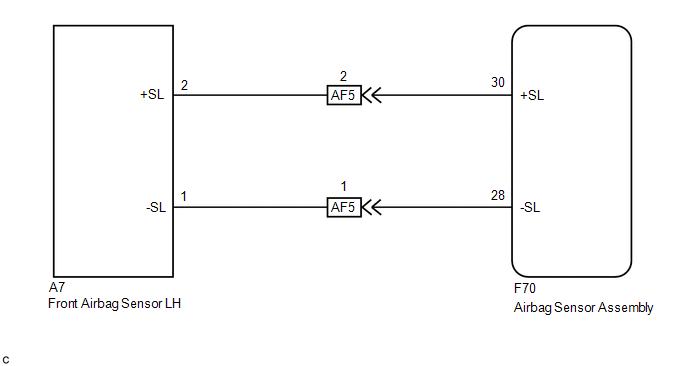
The front airbag sensor LH circuit consists of the airbag sensor assembly and front airbag sensor LH.
The front airbag sensor LH detects impacts to the vehicle and sends signals to the airbag sensor assembly to determine if the airbags and pretensioners should be deployed.
These DTCs are stored when a malfunction is detected in the front airbag sensor LH circuit.
|
DTC No. |
Detection Item |
DTC Detection Condition |
Trouble Area |
Test Mode / Check Mode |
|---|---|---|---|---|
|
B1617/84 |
Lost Communication with Front Airbag Sensor LH |
Any of the following conditions is met:
|
|
Does not apply to test/check mode |
|
B1618/84 |
Front Airbag Sensor LH Initialization Incomplete |
Any of the following conditions is met:
|
|
Does not apply to test/check mode |
|
Vehicle Condition |
|||||||
|---|---|---|---|---|---|---|---|
|
Pattern 1 |
Pattern 2 |
Pattern 3 |
Pattern 4 |
Pattern 5 |
Pattern 6 |
||
|
Diagnosis Condition |
Ignition switch ON |
○ |
○ |
○ |
○ |
○ |
○ |
|
Malfunction Status |
The airbag sensor assembly detects a line short in the front airbag sensor LH circuit |
○ |
- |
- |
- |
- |
- |
|
The airbag sensor assembly detects a short to ground in the front airbag sensor LH circuit |
- |
○ |
- |
- |
- |
- |
|
|
The airbag sensor assembly detects a short to B+ in the front airbag sensor LH circuit |
- |
- |
○ |
- |
- |
- |
|
|
The airbag sensor assembly detects an open in the front airbag sensor LH circuit |
- |
- |
- |
○ |
- |
- |
|
|
Front airbag sensor LH malfunction |
- |
- |
- |
- |
○ |
- |
|
|
Airbag sensor assembly malfunction |
- |
- |
- |
- |
- |
○ |
|
|
Detection Time |
- |
- |
- |
- |
- |
- |
|
|
Number of Trips |
1 trip |
1 trip |
1 trip |
1 trip |
1 trip |
1 trip |
|
|
Vehicle Condition |
|||||||
|---|---|---|---|---|---|---|---|
|
Pattern 1 |
Pattern 2 |
Pattern 3 |
Pattern 4 |
Pattern 5 |
Pattern 6 |
||
|
Diagnosis Condition |
Ignition switch ON |
○ |
○ |
○ |
○ |
○ |
○ |
|
Malfunction Status |
The airbag sensor assembly detects a line short in the front airbag sensor LH circuit |
○ |
- |
- |
- |
- |
- |
|
The airbag sensor assembly detects a short to ground in the front airbag sensor LH circuit |
- |
○ |
- |
- |
- |
- |
|
|
The airbag sensor assembly detects a short to B+ in the front airbag sensor LH circuit |
- |
- |
○ |
- |
- |
- |
|
|
The airbag sensor assembly detects an open in the front airbag sensor LH circuit |
- |
- |
- |
○ |
- |
- |
|
|
Front airbag sensor LH malfunction |
- |
- |
- |
- |
○ |
- |
|
|
Airbag sensor assembly malfunction |
- |
- |
- |
- |
- |
○ |
|
|
Detection Time |
- |
- |
- |
- |
- |
- |
|
|
Number of Trips |
1 trip |
1 trip |
1 trip |
1 trip |
1 trip |
1 trip |
|
HINT:
DTC will be output when conditions for either of the patterns in the table above are met.
WIRING DIAGRAM
CAUTION / NOTICE / HINT
NOTICE:
After turning the ignition switch off, waiting time may be required before disconnecting the cable from the negative (-) battery terminal. Therefore, make sure to read the disconnecting the cable from the negative (-) battery terminal notices before proceeding with work.
Click here .gif)
PROCEDURE
|
1. |
CHECK CONNECTORS |
(a) Turn the ignition switch off.
(b) Disconnect the cable from the negative (-) battery terminal.
CAUTION:
Wait at least 90 seconds after disconnecting the cable from the negative (-) battery terminal to disable the SRS system.
(c) Check that the connectors are properly connected to the airbag sensor assembly and front airbag sensor LH. Also check that the connectors that link the engine room main wire and instrument panel wire are properly connected.
OK:
The connectors are properly connected.
HINT:
If the connectors are not properly connected, reconnect the connectors and proceed to the next inspection.
(d) Disconnect the connectors from the airbag sensor assembly and front airbag sensor LH. Also disconnect the connectors that link the engine room main wire and instrument panel wire.
(e) Check that the terminals of the connectors are not deformed or damaged.
OK:
The terminals are not deformed or damaged.
| NG | .gif) |
REPLACE WIRE HARNESS |
|
.gif)
|
2. |
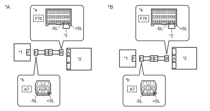
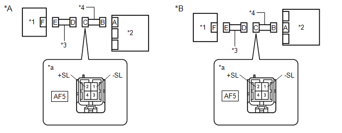
CHECK FRONT AIRBAG SENSOR LH CIRCUIT (OPEN) |
(a) Connect the connectors that link the engine room main wire and instrument panel wire.
|
*A |
w/o Occupant Classification System |
*B |
w/ Occupant Classification System |
|
*1 |
Front Airbag Sensor LH |
*2 |
Airbag Sensor Assembly |
|
*3 |
Service Wire |
- |
- |
|
*a |
Front view of wire harness connector (to Airbag Sensor Assembly) |
*b |
Front view of wire harness connector (to Front Airbag Sensor LH) |
(b) Using a service wire, connect terminals 30 (+SL) and 28 (-SL) of connector B.
NOTICE:
Do not forcibly insert the service wire into the terminals of the connector when connecting the wire.
(c) Measure the resistance according to the value(s) in the table below.
Standard Resistance:
|
Tester Connection |
Condition |
Specified Condition |
|---|---|---|
|
A7-2 (+SL) - A7-1 (-SL) |
Always |
Below 1 Ω |
| NG | |
GO TO STEP 10 |
|
|
3. |
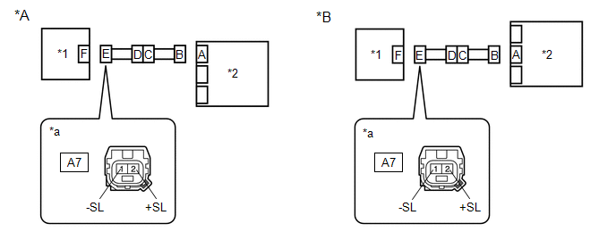
CHECK FRONT AIRBAG SENSOR LH CIRCUIT (SHORT) |
(a) Disconnect the service wire from connector B.
|
*A |
w/o Occupant Classification System |
*B |
w/ Occupant Classification System |
|
*1 |
Front Airbag Sensor LH |
*2 |
Airbag Sensor Assembly |
|
*a |
Front view of wire harness connector (to Front Airbag Sensor LH) |
- |
- |
(b) Measure the resistance according to the value(s) in the table below.
Standard Resistance:
|
Tester Connection |
Condition |
Specified Condition |
|---|---|---|
|
A7-2 (+SL) - A7-1 (-SL) |
Always |
1 MΩ or higher |
| NG | |
GO TO STEP 9 |
|
|
4. |
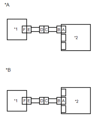
CHECK FRONT AIRBAG SENSOR LH CIRCUIT (SHORT TO B+) |
(a) Connect the cable to the negative (-) battery terminal.

|
*A |
w/o Occupant Classification System |
*B |
w/ Occupant Classification System |
|
*1 |
Front Airbag Sensor LH |
*2 |
Airbag Sensor Assembly |
|
*a |
Front view of wire harness connector (to Front Airbag Sensor LH) |
- |
- |
(b) Turn the ignition switch ON.
(c) Measure the voltage according to the value(s) in the table below.
Standard Voltage:
|
Tester Connection |
Switch Condition |
Specified Condition |
|---|---|---|
|
A7-2 (+SL) - Body ground |
Ignition switch ON |
Below 1 V |
|
A7-1 (-SL) - Body ground |
Ignition switch ON |
Below 1 V |
(d) Turn the ignition switch off.
(e) Disconnect the cable from the negative (-) battery terminal.
CAUTION:
Wait at least 90 seconds after disconnecting the cable from the negative (-) battery terminal to disable the SRS system.
| NG | |
GO TO STEP 8 |
|
|
5. |
CHECK FRONT AIRBAG SENSOR LH CIRCUIT (SHORT TO GROUND) |
(a) Measure the resistance according to the value(s) in the table below.
|
*A |
w/o Occupant Classification System |
*B |
w/ Occupant Classification System |
|
*1 |
Front Airbag Sensor LH |
*2 |
Airbag Sensor Assembly |
|
*a |
Front view of wire harness connector (to Front Airbag Sensor LH) |
- |
- |
Standard Resistance:
|
Tester Connection |
Condition |
Specified Condition |
|---|---|---|
|
A7-2 (+SL) - Body ground |
Always |
1 MΩ or higher |
|
A7-1 (-SL) - Body ground |
Always |
1 MΩ or higher |
| NG | |
GO TO STEP 7 |
|
|
6. |
CHECK FRONT AIRBAG SENSOR LH |
|
(a) Connect the connector to the airbag sensor assembly. |
|
(b) Interchange the front airbag sensor LH with RH and connect the connectors.
(c) Connect the cable to the negative (-) battery terminal.
(d) Clear the DTCs stored in memory.
Click here
(e) Turn the ignition switch off.
(f) Turn the ignition switch ON, and wait for at least 60 seconds.
(g) Check for DTCs.
Click here
HINT:
Codes other than DTCs B1612/83, B1613/83, B1617/84 and B1618/84 may be output at this time, but they are not related to this check.
|
Result |
Proceed to |
|---|---|
|
DTCs B1612/83, B1613/83, B1617/84 and B1618/84 are not output. |
A |
|
DTC B1617/84 or B1618/84 is output. |
B |
|
DTC B1612/83 or B1613/83 is output. |
C |
(h) Turn the ignition switch off.
(i) Disconnect the cable from the negative (-) battery terminal.
CAUTION:
Wait at least 90 seconds after disconnecting the cable from the negative (-) battery terminal to disable the SRS system.
(j) Return the front airbag sensor LH and RH to their original positions and connect the connectors.
| A | |
USE SIMULATION METHOD TO CHECK |
| B | |
REPLACE AIRBAG SENSOR ASSEMBLY |
| C | |
REPLACE FRONT AIRBAG SENSOR LH |
|
7. |
CHECK INSTRUMENT PANEL WIRE (SHORT TO GROUND) |
(a) Disconnect the instrument panel wire connector from the engine room main wire.
|
*A |
w/o Occupant Classification System |
*B |
w/ Occupant Classification System |
|
*1 |
Front Airbag Sensor LH |
*2 |
Airbag Sensor Assembly |
|
*3 |
Engine Room Main Wire |
*4 |
Instrument Panel Wire |
|
*a |
Front view of wire harness connector (to Engine Room Main Wire) |
- |
- |
(b) Measure the resistance according to the value(s) in the table below.
Standard Resistance:
|
Tester Connection |
Condition |
Specified Condition |
|---|---|---|
|
AF5-2 (+SL) - Body ground |
Always |
1 MΩ or higher |
|
AF5-1 (-SL) - Body ground |
Always |
1 MΩ or higher |
| OK | |
REPLACE ENGINE ROOM MAIN WIRE |
| NG | |
REPLACE INSTRUMENT PANEL WIRE |
|
8. |
CHECK INSTRUMENT PANEL WIRE (SHORT TO B+) |
(a) Disconnect the instrument panel wire connector from the engine room main wire.
|
*A |
w/o Occupant Classification System |
*B |
w/ Occupant Classification System |
|
*1 |
Front Airbag Sensor LH |
*2 |
Airbag Sensor Assembly |
|
*3 |
Engine Room Main Wire |
*4 |
Instrument Panel Wire |
|
*a |
Front view of wire harness connector (to Engine Room Main Wire) |
- |
- |
(b) Connect the cable to the negative (-) battery terminal.
(c) Turn the ignition switch ON.
(d) Measure the voltage according to the value(s) in the table below.
Standard Voltage:
|
Tester Connection |
Switch Condition |
Specified Condition |
|---|---|---|
|
AF5-2 (+SL) - Body ground |
Ignition switch ON |
Below 1 V |
|
AF5-1 (-SL) - Body ground |
Ignition switch ON |
Below 1 V |
| OK | |
REPLACE ENGINE ROOM MAIN WIRE |
| NG | |
REPLACE INSTRUMENT PANEL WIRE |
|
9. |
CHECK INSTRUMENT PANEL WIRE (SHORT) |
(a) Disconnect the instrument panel wire connector from the engine room main wire.
|
*A |
w/o Occupant Classification System |
*B |
w/ Occupant Classification System |
|
*1 |
Front Airbag Sensor LH |
*2 |
Airbag Sensor Assembly |
|
*3 |
Engine Room Main Wire |
*4 |
Instrument Panel Wire |
|
*a |
Front view of wire harness connector (to Engine Room Main Wire) |
- |
- |
(b) Measure the resistance according to the value(s) in the table below.
Standard Resistance:
|
Tester Connection |
Condition |
Specified Condition |
|---|---|---|
|
AF5-2 (+SL) - AF5-1 (-SL) |
Always |
1 MΩ or higher |
| OK | |
REPLACE ENGINE ROOM MAIN WIRE |
| NG | |
REPLACE INSTRUMENT PANEL WIRE |
|
10. |
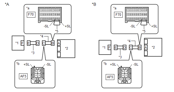
CHECK INSTRUMENT PANEL WIRE (OPEN) |
(a) Disconnect the instrument panel wire connector from the engine room main wire.
|
*A |
w/o Occupant Classification System |
*B |
w/ Occupant Classification System |
|
*1 |
Front Airbag Sensor LH |
*2 |
Airbag Sensor Assembly |
|
*3 |
Engine Room Main Wire |
*4 |
Instrument Panel Wire |
|
*5 |
Service Wire |
- |
- |
|
*a |
Front view of wire harness connector (to Airbag Sensor Assembly) |
*b |
Front view of wire harness connector (to Engine Room Main Wire) |
HINT:
The service wire has already been inserted into connector B.
(b) Measure the resistance according to the value(s) in the table below.
Standard Resistance:
|
Tester Connection |
Condition |
Specified Condition |
|---|---|---|
|
AF5-2 (+SL) - AF5-1 (-SL) |
Always |
Below 1 Ω |
(c) Disconnect the service wire from connector B.
| OK | |
REPLACE ENGINE ROOM MAIN WIRE |
| NG | |
REPLACE INSTRUMENT PANEL WIRE |
 Front Airbag Sensor LH Malfunction (B1615/14)
DESCRIPTION
The front airbag sensor LH circuit consists of the airbag sensor assembly and
front airbag sensor LH.
The front airbag sensor LH detects impacts to the vehicle and sends signals to
t ...
 Lost communication with Side Airbag Sensor RH (B1622/81,B1623/81,B1632/81,B1633/81,B1642/81,B1643/81,B166D/81,B166E/81)
DESCRIPTION
The side collision sensor RH circuit (bus 1) consists of the airbag sensor assembly,
door side airbag sensor RH, No. 1 side airbag sensor RH and No. 2 side airbag sensor
RH.
The door ...
Other materials:
Toyota CH-R Service Manual > Audio And Visual System(for Radio Receiver Type): Portable Player cannot be Connected Manually/Automatically
CAUTION / NOTICE / HINT
HINT:
Some versions of "Bluetooth" compatible audio players may not function properly,
or the functions may be limited using the radio receiver assembly, even if the portable
audio player itself can play files.
Click here
PROCEDURE
1.
...
Toyota CH-R Service Manual > Automatic Light Control Sensor: On-vehicle Inspection
ON-VEHICLE INSPECTION
PROCEDURE
1. INSPECT AUTOMATIC LIGHT CONTROL SENSOR
(a) Check the wire harness.
(1) Disconnect the automatic light control sensor (G1).
(2) Measure the voltage according to the value(s) in the table below.
Standard Voltage:
Tester Connect ...
Toyota C-HR (AX20) 2023-2026 Owner's Manual
Toyota CH-R Owners Manual
- For safety and security
- Instrument cluster
- Operation of each component
- Driving
- Interior features
- Maintenance and care
- When trouble arises
- Vehicle specifications
- For owners
Toyota CH-R Service Manual
- Introduction
- Maintenance
- Audio / Video
- Cellular Communication
- Navigation / Multi Info Display
- Park Assist / Monitoring
- Brake (front)
- Brake (rear)
- Brake Control / Dynamic Control Systems
- Brake System (other)
- Parking Brake
- Axle And Differential
- Drive Shaft / Propeller Shaft
- K114 Cvt
- 3zr-fae Battery / Charging
- Networking
- Power Distribution
- Power Assist Systems
- Steering Column
- Steering Gear / Linkage
- Alignment / Handling Diagnosis
- Front Suspension
- Rear Suspension
- Tire / Wheel
- Tire Pressure Monitoring
- Door / Hatch
- Exterior Panels / Trim
- Horn
- Lighting (ext)
- Mirror (ext)
- Window / Glass
- Wiper / Washer
- Door Lock
- Heating / Air Conditioning
- Interior Panels / Trim
- Lighting (int)
- Meter / Gauge / Display
- Mirror (int)
- Power Outlets (int)
- Pre-collision
- Seat
- Seat Belt
- Supplemental Restraint Systems
- Theft Deterrent / Keyless Entry

0.011