Toyota CH-R Service Manual: Side Airbag Sensor LH Circuit Malfunction (B1625/22)
DESCRIPTION
The side collision sensor LH circuit (bus 1) consists of the airbag sensor assembly, door side airbag sensor LH, No. 1 side airbag sensor LH and No. 2 side airbag sensor LH.
The door side airbag sensor LH, No. 1 side airbag sensor LH and No. 2 side airbag sensor LH detect impacts to the vehicle and send signals to the airbag sensor assembly to determine if the airbags and pretensioners should be deployed.
DTC B1625/22 is stored when a malfunction is detected in the No. 1 side airbag sensor LH.
|
DTC No. |
Detection Item |
DTC Detection Condition |
Trouble Area |
Test Mode / Check Mode |
|---|---|---|---|---|
|
B1625/22 |
Side Airbag Sensor LH Circuit Malfunction |
Any of the following conditions is met:
|
|
Does not apply to test/check mode |
|
Vehicle Condition |
|||
|---|---|---|---|
|
Pattern 1 |
Pattern 2 |
||
|
Diagnosis Condition |
Ignition switch ON |
○ |
○ |
|
Malfunction Status |
No. 1 side airbag sensor LH malfunction |
○ |
- |
|
Airbag sensor assembly malfunction |
- |
○ |
|
|
Detection Time |
- |
- |
|
|
Number of Trips |
1 trip |
1 trip |
|
HINT:
DTC will be output when conditions for either of the patterns in the table above are met.
WIRING DIAGRAM
Click here .gif)
CAUTION / NOTICE / HINT
NOTICE:
After turning the ignition switch off, waiting time may be required before disconnecting the cable from the negative (-) battery terminal. Therefore, make sure to read the disconnecting the cable from the negative (-) battery terminal notices before proceeding with work.
Click here
PROCEDURE
|
1. |
CHECK NO. 1 SIDE AIRBAG SENSOR LH |
|
(a) Turn the ignition switch off. |
|
(b) Disconnect the cable from the negative (-) battery terminal.
CAUTION:
Wait at least 90 seconds after disconnecting the cable from the negative (-) battery terminal to disable the SRS system.
(c) Interchange the No. 1 side airbag sensor LH with RH and connect the connectors.
(d) Connect the cable to the negative (-) battery terminal.
(e) Clear the DTCs stored in memory.
Click here
(f) Turn the ignition switch off.
(g) Turn the ignition switch ON, and wait for at least 60 seconds.
(h) Check for DTCs.
Click here
HINT:
Codes other than DTCs B1620/21 and B1625/22 may be output at this time, but they are not related to this check.
|
Result |
Proceed to |
|---|---|
|
DTC B1625/22 is output. |
A |
|
DTC B1620/21 is output. |
B |
|
DTCs B1620/21 and B1625/22 are not output. |
C |
(i) Turn the ignition switch off.
(j) Disconnect the cable from the negative (-) battery terminal.
CAUTION:
Wait at least 90 seconds after disconnecting the cable from the negative (-) battery terminal to disable the SRS system.
(k) Return the No. 1 side airbag sensor LH and RH to their original positions and connect the connectors.
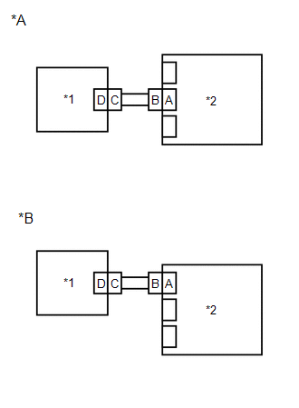
| A | .gif) |
REPLACE AIRBAG SENSOR ASSEMBLY |
| B | |
REPLACE NO. 1 SIDE AIRBAG SENSOR LH |
| C | |
USE SIMULATION METHOD TO CHECK |
 Lost communication with Side Airbag Sensor RH (B1622/81,B1623/81,B1632/81,B1633/81,B1642/81,B1643/81,B166D/81,B166E/81)
DESCRIPTION
The side collision sensor RH circuit (bus 1) consists of the airbag sensor assembly,
door side airbag sensor RH, No. 1 side airbag sensor RH and No. 2 side airbag sensor
RH.
The door ...
 Side Airbag Sensor Assembly No.2 Lost Communication (RH) (B162B/85,B162C/85)
DESCRIPTION
The side collision sensor RH circuit (bus 2) consists of the airbag sensor assembly
and floor side airbag sensor RH.
The floor side airbag sensor RH detects impacts to the vehicle and ...
Other materials:
Toyota CH-R Service Manual > Meter / Gauge System: Problem Symptoms Table
PROBLEM SYMPTOMS TABLE
NOTICE:
When replacing the combination meter assembly, always replace it with a new one.
If a combination meter assembly which was installed to another vehicle is used,
the information stored in it will not match the information from the vehicle and
a DTC may be stored ...
Toyota CH-R Service Manual > Seat Belt Warning System(w/o Occupant Classification System): On-vehicle Inspection
ON-VEHICLE INSPECTION
PROCEDURE
1. INSPECT DRIVER SEAT BELT WARNING SYSTEM
HINT:
The seat belt warning light on the combination meter assembly is used for both
the driver seat and front passenger seat.
(a) Turn the ignition switch to ON.
(b) When the driver seat belt is not fastened, check t ...
Toyota C-HR (AX20) 2023-2026 Owner's Manual
Toyota CH-R Owners Manual
- For safety and security
- Instrument cluster
- Operation of each component
- Driving
- Interior features
- Maintenance and care
- When trouble arises
- Vehicle specifications
- For owners
Toyota CH-R Service Manual
- Introduction
- Maintenance
- Audio / Video
- Cellular Communication
- Navigation / Multi Info Display
- Park Assist / Monitoring
- Brake (front)
- Brake (rear)
- Brake Control / Dynamic Control Systems
- Brake System (other)
- Parking Brake
- Axle And Differential
- Drive Shaft / Propeller Shaft
- K114 Cvt
- 3zr-fae Battery / Charging
- Networking
- Power Distribution
- Power Assist Systems
- Steering Column
- Steering Gear / Linkage
- Alignment / Handling Diagnosis
- Front Suspension
- Rear Suspension
- Tire / Wheel
- Tire Pressure Monitoring
- Door / Hatch
- Exterior Panels / Trim
- Horn
- Lighting (ext)
- Mirror (ext)
- Window / Glass
- Wiper / Washer
- Door Lock
- Heating / Air Conditioning
- Interior Panels / Trim
- Lighting (int)
- Meter / Gauge / Display
- Mirror (int)
- Power Outlets (int)
- Pre-collision
- Seat
- Seat Belt
- Supplemental Restraint Systems
- Theft Deterrent / Keyless Entry

0.0113