Toyota CH-R Service Manual: Removal
REMOVAL
CAUTION / NOTICE / HINT
The necessary procedures (adjustment, calibration, initialization or registration) that must be performed after parts are removed and installed, or replaced during the headlight assembly removal/installation are shown below.
Necessary Procedure After Parts Removed/Installed/Replaced|
Replacement Part or Procedure |
Necessary Procedures |
Effects/Inoperative when not performed |
Link |
|---|---|---|---|
|
Headlight ECU sub-assembly LH |
|
Automatic headlight beam level control system |
|
NOTICE:
If the headlight assembly RH is replaced with a new one, vehicle information registration and initialization are not necessary.
HINT:
- Use the same procedure for the RH side and LH side.
- The following procedure is for the LH side.
PROCEDURE
1. REMOVE FRONT BUMPER ASSEMBLY
Click here
.gif)
2. REMOVE HEADLIGHT ASSEMBLY
(a) Apply protective tape around the headlight assembly as shown in the illustration.
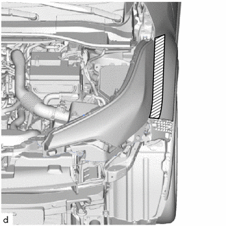
.png) |
Protective Tape |
(b) Disengage the claw, pull down the connector lock lever as shown in the illustration to disconnect the connector.
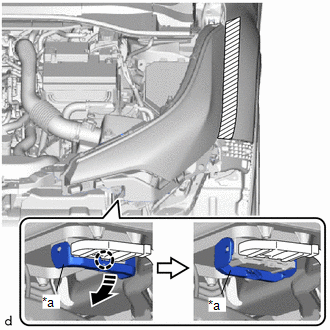
|
*a |
Connector Lock Lever |
.png) |
Remove in this Direction |
|
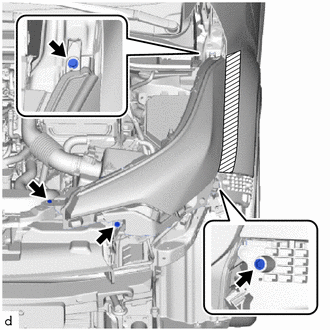
(c) Remove the bolt and 3 screws. |
|
(d) Remove the headlight assembly as shown in the illustration.
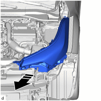
|
|
Remove in this Direction |
 Components
COMPONENTS
ILLUSTRATION
*1
HEADLIGHT ASSEMBLY
-
-
N*m (kgf*cm, ft.*lbf): Specified torque
-
-
...
 Disassembly
DISASSEMBLY
CAUTION / NOTICE / HINT
HINT:
Use the same procedure for the RH side and LH side.
The following procedure is for the LH side.
PROCEDURE
1. REMOVE HEADLIGHT PROTECTOR ...
Other materials:
Toyota CH-R Service Manual > Park / Neutral Position Switch: Installation
INSTALLATION
PROCEDURE
1. INSTALL PARK/NEUTRAL POSITION SWITCH
(a) Temporarily install the park/neutral position switch to the continuously
variable transaxle assembly with the 2 bolts.
(b) Install the lock plate and lock nut to the park/neutral position
switch.
Torque:
6 ...
Toyota CH-R Service Manual > Power Window Control System: Front Passenger Side Power Window does not Operate with Front Passenger Side
Power Window Switch
DESCRIPTION
When the ignition switch is ON, the power window regulator motor assembly (for
front passenger door) is operated by the power window regulator switch assembly.
The power window regulator motor assembly (for front passenger door) has motor,
regulator, and ECU functions.
WIRING DIA ...
Toyota C-HR (AX20) 2023-2026 Owner's Manual
Toyota CH-R Owners Manual
- For safety and security
- Instrument cluster
- Operation of each component
- Driving
- Interior features
- Maintenance and care
- When trouble arises
- Vehicle specifications
- For owners
Toyota CH-R Service Manual
- Introduction
- Maintenance
- Audio / Video
- Cellular Communication
- Navigation / Multi Info Display
- Park Assist / Monitoring
- Brake (front)
- Brake (rear)
- Brake Control / Dynamic Control Systems
- Brake System (other)
- Parking Brake
- Axle And Differential
- Drive Shaft / Propeller Shaft
- K114 Cvt
- 3zr-fae Battery / Charging
- Networking
- Power Distribution
- Power Assist Systems
- Steering Column
- Steering Gear / Linkage
- Alignment / Handling Diagnosis
- Front Suspension
- Rear Suspension
- Tire / Wheel
- Tire Pressure Monitoring
- Door / Hatch
- Exterior Panels / Trim
- Horn
- Lighting (ext)
- Mirror (ext)
- Window / Glass
- Wiper / Washer
- Door Lock
- Heating / Air Conditioning
- Interior Panels / Trim
- Lighting (int)
- Meter / Gauge / Display
- Mirror (int)
- Power Outlets (int)
- Pre-collision
- Seat
- Seat Belt
- Supplemental Restraint Systems
- Theft Deterrent / Keyless Entry

0.007