Toyota CH-R Service Manual: System Description
SYSTEM DESCRIPTION
GENERAL
The air conditioning system has the following controls.
|
Control |
Outline |
|---|---|
|
Neural Network Control |
This control is capable of performing complex control by artificially simulating the information processing method of the nervous system of living organisms in order to establish a complex input/output relationship similar to that of a human brain. |
|
Outlet Air Temperature Control |
Based on the temperature set by the temperature control dial, neural network control calculates outlet air temperature based on input signals from various sensors. |
|
Left and Right Independent Control |
The temperature settings for the driver and front passenger are controlled independently in order to provide separate vehicle interior temperatures for the right and left sides of the vehicle. Thus, air conditioning that accommodates the occupants' preferences has been realized. |
|
Blower Control |
Controls the blower motor in accordance with the airflow volume that has been calculated by neural network control based on input signals from various sensors. |
|
Air Outlet Control |
Automatically switches the air outlets in accordance with the outlet mode that has been calculated by neural network control. |
|
In accordance with the engine coolant temperature, ambient air temperature, amount of sunlight, required blower, outlet temperature and vehicle speed conditions, this control automatically switches the blower outlet to foot/defroster mode to prevent the windows from becoming fogged up when the ambient air temperature is low. |
|
|
Air Inlet Control |
Automatically controls the air inlet control damper to help achieve the calculated outlet air temperature that is required. |
|
Drives the air inlet control servo motor according to the operation of the air inlet control switch and moves the dampers to the fresh or recirculation position. |
|
|
Variable Capacity Compressor Control |
Controls the compressor with pulley assembly to turn it on or off and adjust the discharge capacity based on the signals from various sensors. |
|
Defroster Control |
Defroster control logic is used to improve defroster performance. |
|
Parking Fresh Control |
By automatically switching to fresh air mode when the vehicle is parked. Ventilation of the parked vehicle is facilitated and outside air is introduced into the air conditioner unit assembly. |
|
Blower Customize |
During automatic air conditioning operation, the air volume can be adjusted in 3 levels using the air conditioning control assembly (FAST/ECO switch): NORMAL → ECO (small air volume) → FAST (large air volume). |
|
Diagnosis |
A Diagnostic Trouble Code (DTC) is stored in memory when the air conditioning amplifier assembly detects a problem with the air conditioning system. |
NEURAL NETWORK CONTROL
- In previous automatic air conditioning systems, the air conditioning
amplifier assembly determined the required outlet air temperature and blower
air volume in accordance with the calculation formula that has been obtained
based on information received from the sensors.
However, because the senses of a person are rather complex, a given temperature is sensed differently, depending on the environment in which the person is situated. For example, a given amount of solar radiation can feel comfortably warm in a cold climate, or extremely uncomfortable in a hot climate. Therefore, as a technique for effecting a higher level of control, a neural network has been adopted in the automatic air conditioning system. With this technique, the data that has been collected under varying environmental conditions is stored in the air conditioning amplifier assembly. The air conditioning amplifier assembly can then effect control to provide enhanced air conditioning comfort.
- The neural network control consists of neurons in the input layer, intermediate layer and output layer. The input layer neurons process the input data of the outside temperature, the amount of sunlight and the room temperature based on the outputs of the switches and sensors, and output them to the intermediate layer neurons. Based on this data, the intermediate layer neurons adjust the strength of the links among the neurons. The sum of these is then calculated by the output layer neurons in the form of the required outlet temperature, solar correction, target airflow volume and outlet mode control volume. Accordingly, the air conditioning amplifier assembly controls the servo motors and blower motor in accordance with the control volumes that have been calculated by the neural network control.
.png)
MODE POSITION AND DAMPER OPERATION
Mode Position and Damper Operation
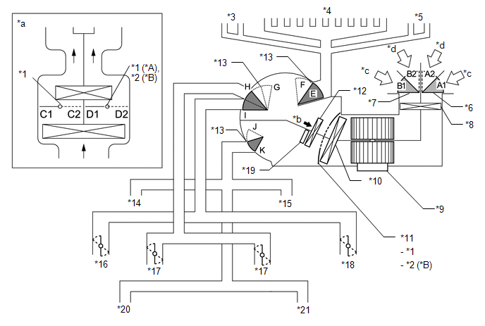
|
*A |
for Manual Air Conditioning System |
*B |
for Automatic Air Conditioning System |
|
*1 |
Driver Side Air Mix Control Damper |
*2 |
Front Passenger Side Air Mix Control Damper |
|
*3 |
Driver Side Defroster |
*4 |
Front Defroster |
|
*5 |
Front Passenger Side Defroster |
*6 |
Air Inlet Control Damper (Lower Side) |
|
*7 |
Air Inlet Control Damper (Upper Side) |
*8 |
Clean Air Filter |
|
*9 |
Blower with Fan Motor Sub-assembly |
*10 |
No. 1 Cooler Evaporator Sub-assembly |
|
*11 |
Air Mix Control Damper |
*12 |
Heater Radiator Unit Sub-assembly |
|
*13 |
Mode Switching Damper |
*14 |
Driver Side Footwell Register |
|
*15 |
Front Passenger Side Footwell Register |
*16 |
Driver Side Register |
|
*17 |
Center Register |
*18 |
Front Passenger Side Register |
|
*19 |
Quick Heater Assembly |
*20 |
Rear Footwell Register LH |
|
*21 |
Rear Footwell Register RH |
- |
- |
|
*a |
Illustration Image View from [A] |
*b |
[A] View |
|
*c |
Recirculated Air |
*d |
Fresh Air |
|
Control Damper |
Operation Position |
Damper Position |
Operation |
|---|---|---|---|
|
Air Inlet Control Damper |
FRESH |
A1 |
Allows fresh air to enter. |
|
RECIRCULATION |
A2 |
Causes internal air to recirculate. |
|
|
Air Mix Control Damper |
HI - LO |
B1 - B2 |
Varies the driver side mixture ratio of cool air and hot air in order to regulate the temperature continuously from HI to LO. |
|
C2 - C1 |
Varies the front passenger side mixture ratio of cool air and hot air in order to regulate the temperature continuously from HI to LO. |
||
|
Air Outlet Control Damper |
DEF .png) |
E, G, J |
Defrosts the windshield through the center defroster, side defrosters and side registers. |
|
FOOT/DEF .png) |
E, G, I to J |
Defrosts the windshield through the center defroster, side defrosters and side registers, while air is also blown out from the front footwell register ducts. |
|
|
FOOT .png) |
D, (D to E), G, I |
Air blows out of the front footwell register ducts and side registers. In addition, air blows out slightly from the center defroster and side defrosters. |
|
|
B/L .png) |
D, F to H, I to J |
Air blows out of the center registers, side registers and front footwell register ducts. |
|
|
FACE .png) |
D, F, J |
Air blows out of the center registers and side registers. |
AIR OUTLETS AND AIRFLOW VOLUME
The size of each circle ○ indicates the ratio of airflow volume.
(a) Air Outlets and Airflow Volume.
.png)
|
Mode |
FACE |
FOOT |
DEF |
|||
|---|---|---|---|---|---|---|
|
Center |
Side |
Front |
Rear*1 |
Center |
Side |
|
|
A |
B |
C |
D |
E |
F |
|
|
FACE |
.png) |
|
.png) |
|
|
|
|
B/L |
.png) |
|
|
|
|
.png) |
|
FOOT |
|
|
|
|
|
|
|
FOOT/DEF |
|
|
|
|
|
|
|
DEF |
|
|
|
|
|
|
- *1: w/ PTC Heater
FRESH AIR INTRODUCTION WHILE PARKING CONTROL
When 60 seconds have elapsed since the ignition switch has been turned off, the air conditioning amplifier assembly uses control logic which automatically changes the air inlet to FRESH mode to purge undesired odors from the air conditioning unit.
This logic will therefore reduce undesired odors upon starting the air conditioning system.
.png)
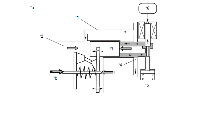
COMPRESSOR
(a) General:
(1) The compressor is a continuously variable capacity type in which its capacity can be varied in accordance with the cooling load of the air conditioning system.
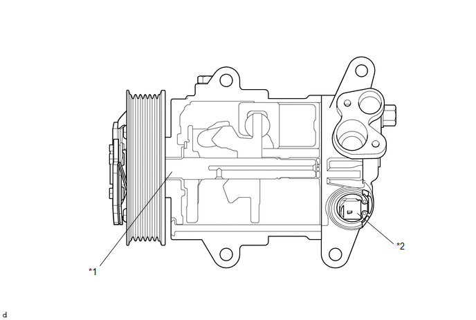
|
*1 |
Shaft |
*2 |
Solenoid Control Valve |
(b) Solenoid Valve Operation:
(1) The crank chamber is connected to the suction passage. A solenoid valve is provided between the suction passage (low pressure) and the discharge passage (high pressure).
(2) The solenoid valve operates under duty cycle control in accordance with the signals from the air conditioning amplifier assembly.
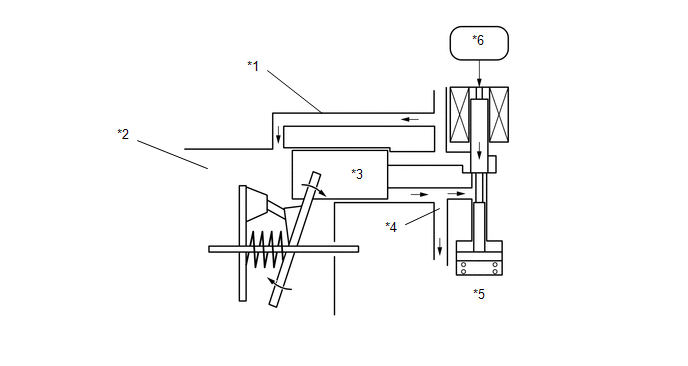
|
*1 |
Suction Passage |
*2 |
Crank Chamber |
|
*3 |
Piston |
*4 |
Discharge Passage |
|
*5 |
Solenoid Control Valve |
*6 |
Air Conditioning Amplifier Assembly |
(3) When the solenoid valve closes (solenoid coil is energized), a difference in pressure is created and the pressure in the crank chamber decreases. Then, the pressure that is applied to the right side of the piston becomes greater than the pressure that is applied to the left side of the piston. This compresses the spring and tilts the swash plate. As a result, the piston stroke increases and the discharge capacity also increases.
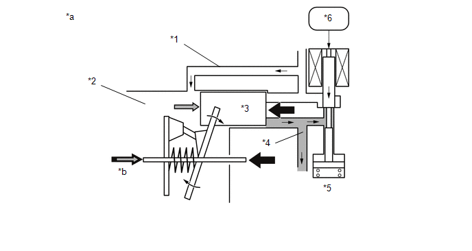
|
*1 |
Suction Passage |
*2 |
Crank Chamber |
|
*3 |
Piston |
*4 |
Discharge Passage |
|
*5 |
Solenoid Control Valve |
*6 |
Air Conditioning Amplifier Assembly |
|
*a |
Piston Stroke: Large |
*b |
Crank Chamber Pressure + Spring Force |
(4) When the solenoid valve opens (solenoid coil is not energized), the difference in pressure disappears. Then, the pressure that is applied to the left side of the piston becomes the same as the pressure that is applied to the right side of the piston. Thus, the spring elongates and eliminates the tilt of the swash plate. As a result, there is no piston stroke, and the discharge capacity is reduced.
|
*1 |
Suction Passage |
*2 |
Crank Chamber |
|
*3 |
Piston |
*4 |
Discharge Passage |
|
*5 |
Solenoid Control Valve |
*6 |
Air Conditioning Amplifier Assembly |
|
*a |
Piston Stroke: Small |
*b |
Crank Chamber Pressure + Spring Force |
(c) CS Valve Operation:
(1) The CS valve consists of passage A and passage B. If the vehicle is left parked for a long period, refrigerant may accumulate in the crank chamber due to the heat capacity difference.
(2) The solenoid control valve is controlled by the air conditioning amplifier assembly. While the compressor is operating, the solenoid control valve pushes down the CS valve rod and opens passage A.
(3) Under the above condition, only if the refrigerant accumulates in the crank chamber, the crank chamber pressure will become high. As a result, the bellows will contract because of the pressure difference with its internal pressure (vacuum), and opens passage B.
(4) This causes the accumulated refrigerant to be drawn in via passage A and passage B, clearing the accumulated refrigerant earlier and ensuring a more immediate cooling effect.
ION GENERATOR SUB-ASSEMBLY (w/ Ion Generator)
(a) The ion generator sub-assembly operates when the blower switch are on.
(b) The ion generator sub-assembly emits "nanoe" ions that are electrically charged and encapsulated with water. The ions are discharged into the cabin through the side register (front passenger side) to provide skin-friendly clean air.*
CAUTION:
Do not attempt to disassemble or repair the ion generator sub-assembly because it contains high voltage parts.
NOTICE:
Do not insert anything into the side register (front passenger side), attach anything to it, or use sprays around it. Doing so may cause the ion generator sub-assembly to not work properly.
HINT:
- *: According to the temperature and humidity conditions, fan speed and air outlet mode selected, the ion generator sub-assembly may not operate at full capacity.
- When the ion generator sub-assembly operates, a small amount of ozone is emitted and may be faintly smelled in some situations. However, this is approximately the same as the amount that already exists in nature, such as in forests, and as such has no effect on the human body.
- A slight noise may be heard during operation. This does not indicate a malfunction.
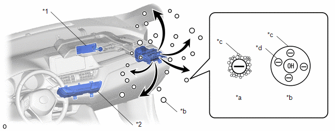
|
*1 |
Ion Generator Sub-assembly |
*2 |
Air Conditioning Control Assembly (nanoe indicator) |
|
*a |
Common Negative Ion |
*b |
"nanoe" Ion |
|
*c |
H2O |
*d |
Electron |
HINT:
"nanoe" is a trademark of Panasonic Co., Ltd.
NO. 1 COOLER THERMISTOR (EVAPORATOR TEMPERATURE SENSOR)
The No. 1 cooler thermistor (evaporator temperature sensor) detects the temperature of the cool air immediately after the evaporator in the form of resistance changes, and outputs it to the air conditioning amplifier assembly.
BLOWER MOTOR WITH FAN SUB-ASSEMBLY
The blower motor is controlled using duty control performed via the blower resistor from the air conditioning amplifier assembly.
BLOWER RESISTOR
The blower resistor controls the blower motor with fan sub-assembly based on changes in the signal sent by the air conditioning amplifier assembly.
SERVO MOTOR
Servo motor, uses a step motor type. The motor inside of four coils have always added the battery voltage. An air conditioning amplifier assembly is as many times as necessary until the position of the target, move the voltage of each of the coil to the position of the target repeat the ON and OFF in order.
QUICK HEATER ASSEMBLY (w/ PTC Heater)
(a) General
(1) The quick heater assembly is located above the heater core in the air conditioning radiator assembly.
(2) The quick heater assembly consists of a PTC element, aluminum fins, and brass plates. When current is applied to the PTC element, it generates heat to warm the air that passes through the unit.
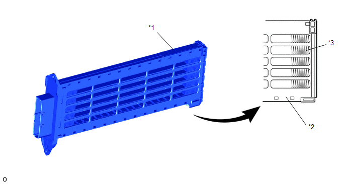
|
*1 |
Quick Heater Assembly |
*2 |
Heat Resistant Resin Plate |
|
*3 |
Fin |
- |
- |
(b) Quick Heater Assembly Operating Conditions
(1) The quick heater assembly is turned on and off by the air conditioning amplifier assembly in accordance with the engine coolant temperature, ambient temperature, temperature setting, and electrical load (generator power ratio).
COOLER THERMISTOR (ROOM TEMPERATURE SENSOR)
The cooler thermistor (room temperature sensor) detects the cabin temperature based on changes in the resistance of its built-in thermistor and sends a signal to the air conditioning amplifier assembly.
THERMISTOR ASSEMBLY
The thermistor assembly detects the outside temperature based on changes in the resistance of its built-in thermistor and sends a signal to the combination meter assembly and via CAN communication, it sends the outside temperature information to air conditioning amplifier assembly.
AUTOMATIC LIGHT CONTROL SENSOR
The automatic light control sensor detects (in the form of changes in the current that flows through the built-in photo diode) the changes in the amount of sunlight and outputs these sunlight strength signals to the air conditioning amplifier assembly.
AIR CONDITIONER PRESSURE SENSOR
The air conditioner pressure sensor detects the refrigerant pressure and outputs it to the air conditioning amplifier assembly in the form of voltage changes.
 System Diagram
SYSTEM DIAGRAM
Communication Table
Sender
Receiver
Signal
Communication Line
Air conditioning amplifier assembly
...
 Customize Parameters
CUSTOMIZE PARAMETERS
CUSTOMIZE AIR CONDITIONING SYSTEM
(a) Customizing with the Techstream.
NOTICE:
When the customer requests a change in a function, first make sure that
the function ...
Other materials:
Toyota CH-R Service Manual > Power Door Lock Control System: All Doors LOCK/UNLOCK Functions do not Operate Via Door Control Switch or Door
Key Cylinder
DESCRIPTION
The main body ECU (multiplex network body ECU) receives switch signals from the
multiplex network master switch assembly and driver door key cylinder lock or unlock
switch signals from the front door lock with motor assembly LH. The main body ECU
(multiplex network body ECU) activ ...
Toyota CH-R Service Manual > Immobiliser System(w/o Smart Key System): Parts Location
PARTS LOCATION
ILLUSTRATION
*1
ECM
*2
NO. 1 ENGINE ROOM RELAY BLOCK
ILLUSTRATION
*1
UNLOCK WARNING SWITCH ASSEMBLY
*2
SECURITY INDICATOR LIGHT (CLOCK ASSEMBLY)
*3
INST ...
Toyota C-HR (AX20) 2023-2026 Owner's Manual
Toyota CH-R Owners Manual
- For safety and security
- Instrument cluster
- Operation of each component
- Driving
- Interior features
- Maintenance and care
- When trouble arises
- Vehicle specifications
- For owners
Toyota CH-R Service Manual
- Introduction
- Maintenance
- Audio / Video
- Cellular Communication
- Navigation / Multi Info Display
- Park Assist / Monitoring
- Brake (front)
- Brake (rear)
- Brake Control / Dynamic Control Systems
- Brake System (other)
- Parking Brake
- Axle And Differential
- Drive Shaft / Propeller Shaft
- K114 Cvt
- 3zr-fae Battery / Charging
- Networking
- Power Distribution
- Power Assist Systems
- Steering Column
- Steering Gear / Linkage
- Alignment / Handling Diagnosis
- Front Suspension
- Rear Suspension
- Tire / Wheel
- Tire Pressure Monitoring
- Door / Hatch
- Exterior Panels / Trim
- Horn
- Lighting (ext)
- Mirror (ext)
- Window / Glass
- Wiper / Washer
- Door Lock
- Heating / Air Conditioning
- Interior Panels / Trim
- Lighting (int)
- Meter / Gauge / Display
- Mirror (int)
- Power Outlets (int)
- Pre-collision
- Seat
- Seat Belt
- Supplemental Restraint Systems
- Theft Deterrent / Keyless Entry

0.0118