Toyota CH-R Service Manual: System Diagram
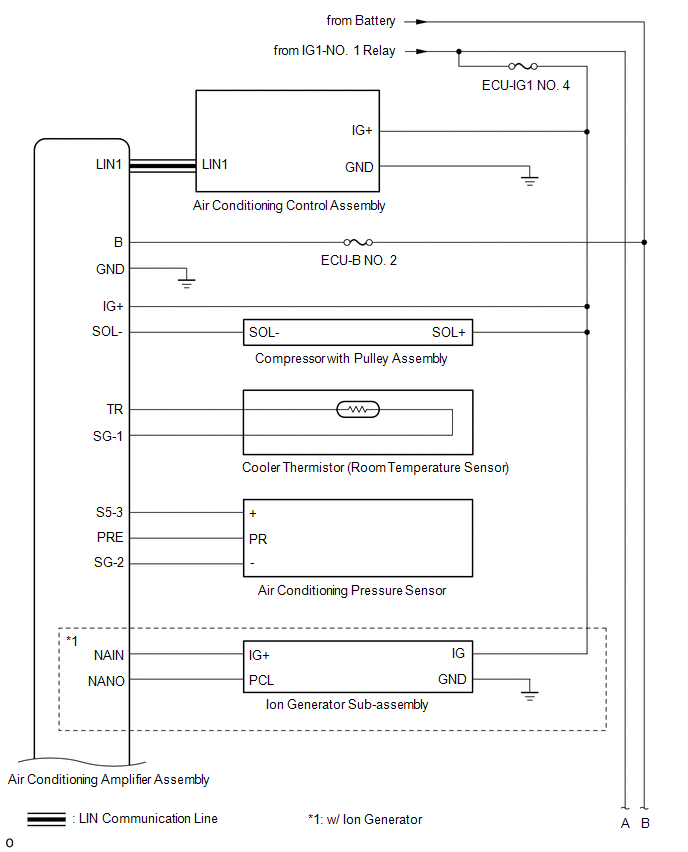
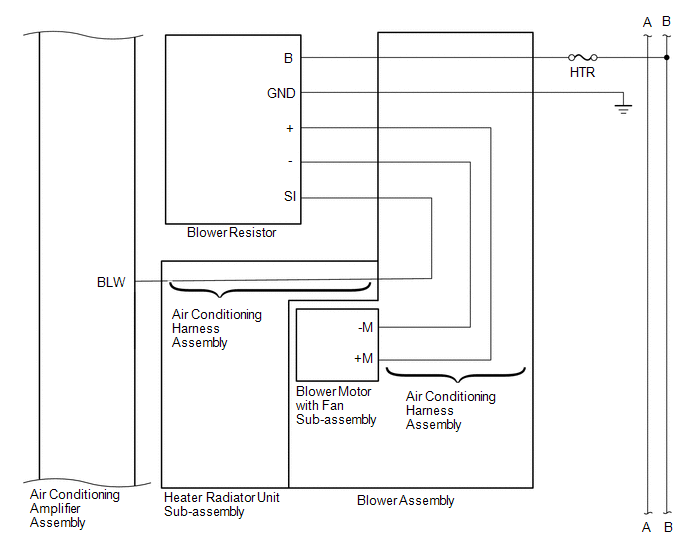
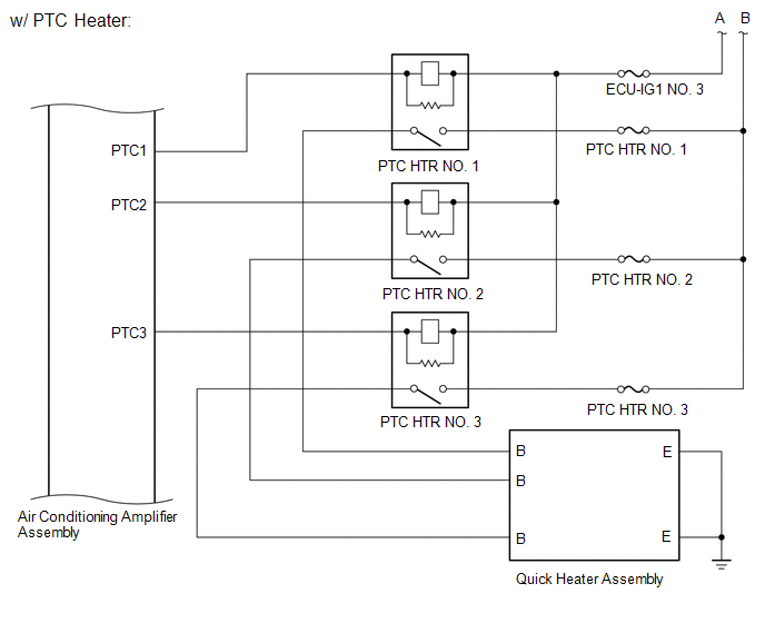
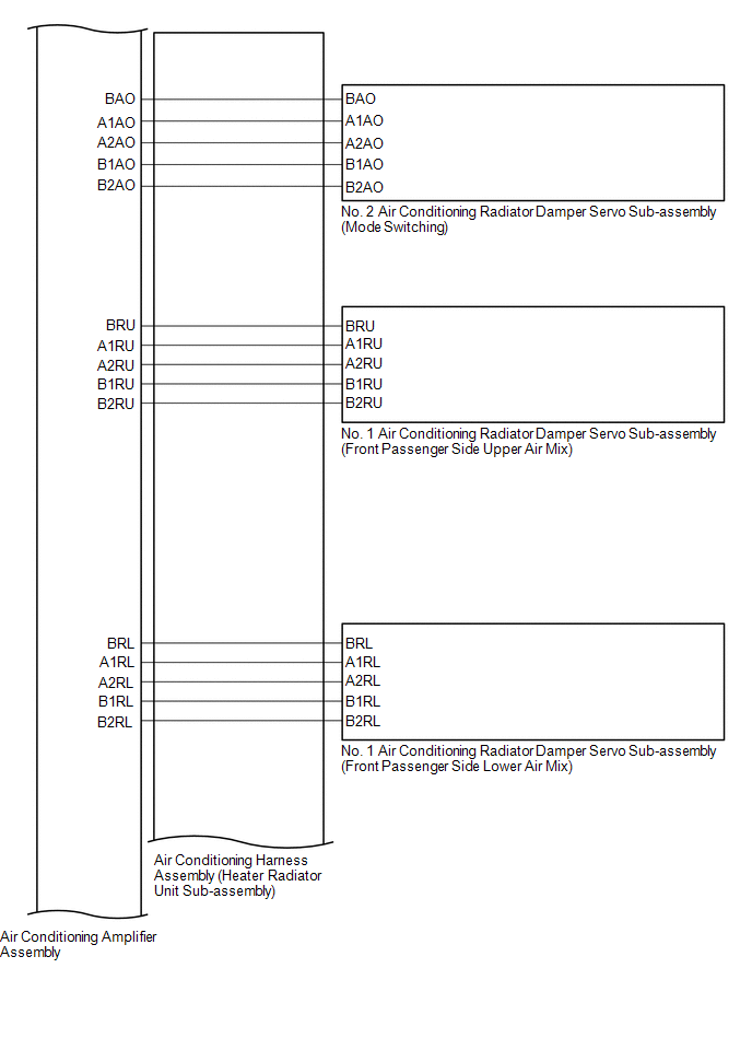
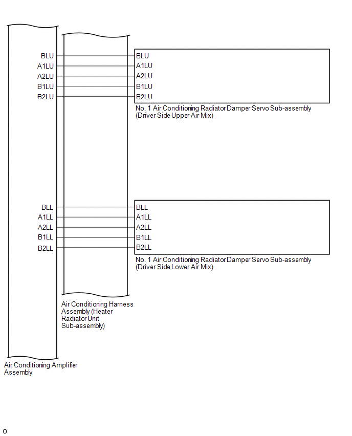
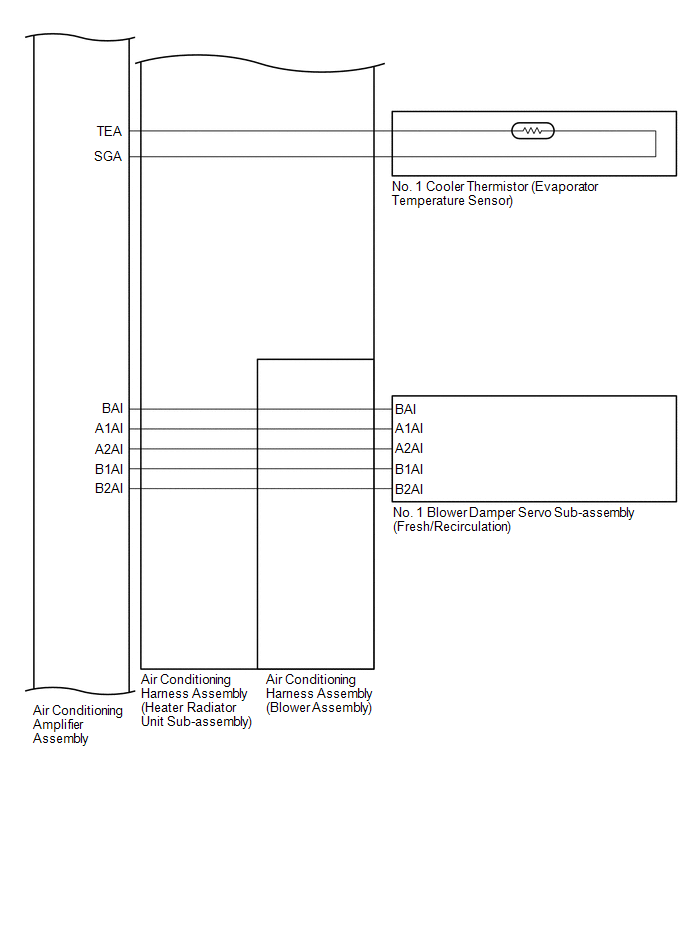
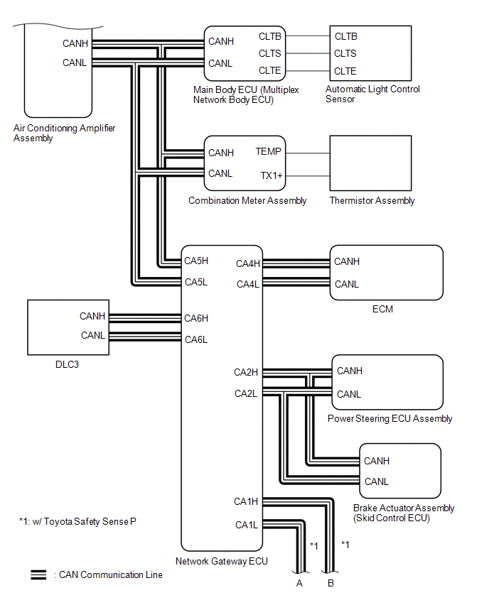
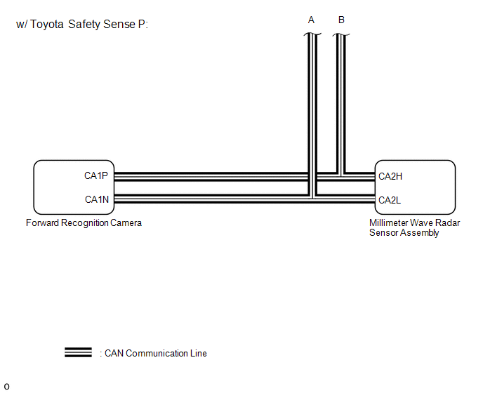
SYSTEM DIAGRAM
 Communication Table
|
Sender |
Receiver |
Signal |
Communication Line |
|---|---|---|---|
|
Air conditioning amplifier assembly |
ECM |
Magnet Clutch request signal |
CAN |
|
A/C idle up request signal |
|||
|
Heater idle up request signal |
|||
|
Blower on state signal |
|||
|
Super cooling control state signal |
|||
|
Charging control inhibit signal |
|||
|
Motor Cooling Fan drive request signal |
|||
|
Prior A/C control request signal |
|||
|
Acceleration Cut inhibit signal |
|||
|
LOCK-UP inhibit signal |
|||
|
PTC Heater control request signal*1 |
|||
|
Generator control inhibit signal |
|||
|
Request control by Refrigerant |
|||
|
Ambient temperature before correction, signal |
|||
|
Refrigerant information |
|||
|
The first advancement evaporator temperature |
|||
|
Electricity load at Low Voltage, state signal |
|||
|
Variable compressor solenoid current signal |
|||
|
Refrigerant gas pressure sensor signal |
|||
|
Rr DEF drive request signal |
|||
|
Ambient temperature display signal |
|||
|
Air conditioning amplifier assembly |
Combination meter assembly |
A/C control state signal |
CAN |
|
Air conditioning amplifier assembly |
Brake actuator assembly (Skid control ECU) |
In-Vehicle temperature signal |
CAN |
|
Ambient temperature display signal |
|||
|
Air conditioning amplifier assembly |
Forward recognition camera*2 |
Ambient temperature display signal |
CAN |
|
Air conditioning amplifier assembly |
Millimeter wave radar sensor assembly*2 |
Ambient temperature display signal |
CAN |
|
ECM |
Air conditioning amplifier assembly |
Drive Mode Select Signal |
CAN |
|
Engine type information 1 |
|||
|
Engine type information 2 |
|||
|
Engine type information 3 |
|||
|
Engine type information 4 |
|||
|
Transmission information |
|||
|
Engine RPM data |
|||
|
Water temperature signal |
|||
|
Alternative field duty value |
|||
|
A/C control cut-off signal 4 |
|||
|
A/C control cut-off signal 3 |
|||
|
A/C control cut-off signal 2 |
|||
|
A/C control cut-off signal 1 |
|||
|
Variable control inhibition signal |
|||
|
Air conditioner cut-off instruction flag at deceleration |
|||
|
A/C super cooling command flag at deceleration |
|||
|
A/C lubrication control inhibit |
|||
|
Compulsory internal air circulation command signal at high water temperature |
|||
|
Main body ECU (multiplex network body ECU) |
Air conditioning amplifier assembly |
Auto dimmer signal |
CAN |
|
High beam head light request |
|||
|
Low beam head light request |
|||
|
Taillight request |
|||
|
Destination Symbol |
|||
|
Destination Package1 |
|||
|
Destination Package2 |
|||
|
Steering Wheel |
|||
|
Solar data(R) |
|||
|
Solar data(L) |
|||
|
Combination meter assembly |
Air conditioning amplifier assembly |
Ambient Temp Display |
CAN |
|
Outside temperature sensor data |
|||
|
Vehicle speed signal (meter to other) |
|||
|
Power steering ECU assembly |
Air conditioning amplifier assembly |
Loading control level |
CAN |
|
Air conditioning amplifier assembly |
Air conditioning control assembly |
Blower customization indication request signal |
LIN |
|
Entire panel indication request signal |
|||
|
AUTO indication request signal |
|||
|
Blower level indication request signal |
|||
|
REC indication request signal |
|||
|
Driver seat side outlet indication request signal |
|||
|
FrDEF indication request (deicer) signal*3 |
|||
|
RrDEF indication request signal |
|||
|
DUAL-SYNC indication request signal |
|||
|
Driver's seat set temperature indication request signal |
|||
|
Passenger's seat set temperature indication request signal |
|||
|
Dimming signal |
|||
|
Nanoe indication request signal*4 |
|||
|
A/C indication request signal |
|||
|
Air conditioning control assembly |
Air conditioning amplifier assembly |
Individual control A/C information signal |
LIN |
|
AUTO operation switch signal |
|||
|
OFF operation switch signal |
|||
|
A/C operation switch signal |
|||
|
Front blower operation switch signal |
|||
|
Blower customize operation switch signal |
|||
|
Driver side outlet related operation switch signal |
|||
|
DEF operation switch signal |
|||
|
RrDEF operation switch signal |
|||
|
DUAL-SYNC operation switch signal |
|||
|
Driver's seat set temperature signal |
|||
|
Passenger's seat set temperature signal |
|||
|
Injection related area operation switch signal |
- *1: w/ PTC Heater
- *2: w/ Toyota Safety Sense P
- *3: w/ Windshield Deicer
- *4: w/ Ion Generator
 Parts Location
PARTS LOCATION
ILLUSTRATION
*A
w/ PTC Heater
*B
w/ Toyota Safety Sense P
*1
AIR CONDITIONER PRESSURE SENSOR
*2
...
 System Description
SYSTEM DESCRIPTION
GENERAL
The air conditioning system has the following controls.
Control
Outline
Neural Network Control
This control is capable o ...
Other materials:
Toyota CH-R Service Manual > Continuously Variable Transaxle System: Torque Converter Clutch Circuit Performance or Stuck OFF (P0741,P075B,P2757)
DESCRIPTION
The ECM uses the shift solenoid valves SC and SL to switch control of the shift
solenoid valve SLU between forward and reverse clutch control and lock-up control
in response to driving conditions.
HINT:
If DTC P0741 is stored after the engine has stalled, the lock-up shift solenoi ...
Toyota CH-R Service Manual > Smart Key System(for Entry Function): Entry Interior Alarm does not Sound
DESCRIPTION
The smart key system (for Entry Function) uses the buzzer in the combination
meter assembly (meter ECU) to perform various vehicle interior warnings. When the
conditions of each warning are met, the certification ECU (smart key ECU assembly)
sends a buzzer activation request signa ...
Toyota C-HR (AX20) 2023-2026 Owner's Manual
Toyota CH-R Owners Manual
- For safety and security
- Instrument cluster
- Operation of each component
- Driving
- Interior features
- Maintenance and care
- When trouble arises
- Vehicle specifications
- For owners
Toyota CH-R Service Manual
- Introduction
- Maintenance
- Audio / Video
- Cellular Communication
- Navigation / Multi Info Display
- Park Assist / Monitoring
- Brake (front)
- Brake (rear)
- Brake Control / Dynamic Control Systems
- Brake System (other)
- Parking Brake
- Axle And Differential
- Drive Shaft / Propeller Shaft
- K114 Cvt
- 3zr-fae Battery / Charging
- Networking
- Power Distribution
- Power Assist Systems
- Steering Column
- Steering Gear / Linkage
- Alignment / Handling Diagnosis
- Front Suspension
- Rear Suspension
- Tire / Wheel
- Tire Pressure Monitoring
- Door / Hatch
- Exterior Panels / Trim
- Horn
- Lighting (ext)
- Mirror (ext)
- Window / Glass
- Wiper / Washer
- Door Lock
- Heating / Air Conditioning
- Interior Panels / Trim
- Lighting (int)
- Meter / Gauge / Display
- Mirror (int)
- Power Outlets (int)
- Pre-collision
- Seat
- Seat Belt
- Supplemental Restraint Systems
- Theft Deterrent / Keyless Entry

0.009