Toyota CH-R Service Manual: Ambient Illumination Light Circuit
DESCRIPTION
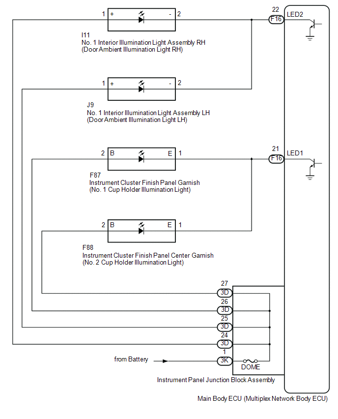
The main body ECU (multiplex network body ECU) controls the ambient illumination lights.
WIRING DIAGRAM
CAUTION / NOTICE / HINT
NOTICE:
- Inspect the lights for circuits related to this system before performing the following procedure.
- Before replacing the main ECU (multiplex network body ECU), refer to
Registration*1.
Click here
.gif)
- *1: w/ Smart Key System
PROCEDURE
|
1. |
PERFORM ACTIVE TEST USING TECHSTREAM |
(a) Connect the Techstream to the DLC3.
(b) Turn the ignition switch to ON.
(c) Turn the Techstream on.
(d) Enter the following menus: Body Electrical / Main Body / Active Test.
(e) Perform the Active Test according to the display on the Techstream.
Body Electrical > Main Body > Active Test|
Tester Display |
Measurement Item |
Control Range |
Diagnostic Note |
|---|---|---|---|
|
Interior Illumination Light1 |
|
ON or OFF |
Preconditions for using the Active Test to check dimmer controlled illumination:
|
|
Interior Illumination Light2 |
|
ON or OFF |
Preconditions for using the Active Test to check dimmer controlled illumination:
|
|
Tester Display |
|---|
|
Interior Illumination Light1 |
|
Tester Display |
|---|
|
Interior Illumination Light2 |
OK:
Ambient illumination lights comes on.
|
Result |
Proceed to |
|---|---|
|
OK |
A |
|
NG (All ambient lights do not illuminate) |
B |
|
NG (Cup holder illumination light does not illuminate) |
C |
|
NG (Door ambient illumination light does not illuminate) |
D |
| A | .gif) |
PROCEED TO NEXT SUSPECTED AREA SHOWN IN PROBLEM SYMPTOMS TABLE |
| C | |
GO TO STEP 4 |
| D | |
GO TO STEP 7 |
|
.gif)
|
2. |
CHECK HARNESS AND CONNECTOR (POWER SOURCE - INSTRUMENT PANEL JUNCTION BLOCK ASSEMBLY) |
(a) Disconnect the instrument panel junction block assembly connector.
|
(b) Measure the voltage according to the value(s) in the table below. Standard Voltage:
|
|
| NG | |
REPAIR OR REPLACE HARNESS OR CONNECTOR |
|
|
3. |
INSPECT INSTRUMENT PANEL JUNCTION BLOCK ASSEMBLY |
(a) Disconnect the 3D instrument panel junction block assembly connector.
(b) Measure the resistance according to the value(s) in the table below.
|
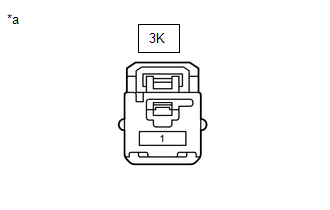
*a |
Component without harness connected (Instrument Panel Junction Block Assembly) |
- |
- |
Standard Resistance:
|
Tester Connection |
Condition |
Specified Condition |
|---|---|---|
|
3K-1 - 3D-24 |
Always |
Below 1 Ω |
|
3K-1 - 3D-25 |
Always |
Below 1 Ω |
|
3K-1 - 3D-26 |
Always |
Below 1 Ω |
|
3K-1 - 3D-27 |
Always |
Below 1 Ω |
| OK | |
PROCEED TO NEXT SUSPECTED AREA SHOWN IN PROBLEM SYMPTOMS TABLE |
| NG | |
REPLACE INSTRUMENT PANEL JUNCTION BLOCK ASSEMBLY |
|
4. |
INSPECT INSTRUMENT PANEL JUNCTION BLOCK ASSEMBLY |
(a) Disconnect the 3D instrument panel junction block assembly connector.
(b) Disconnect the 3K instrument panel junction block assembly connector.
(c) Measure the resistance according to the value(s) in the table below.
|
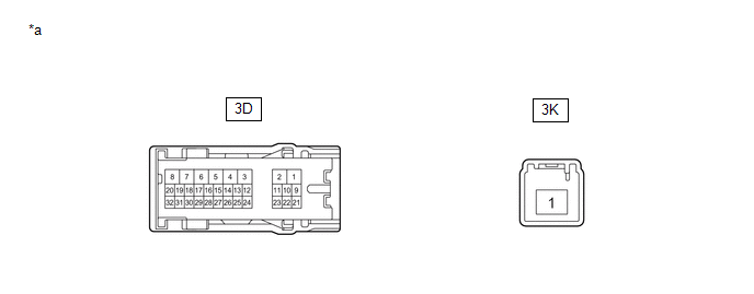
*a |
Component without harness connected (Instrument Panel Junction Block Assembly) |
- |
- |
Standard Resistance:
|
Tester Connection |
Condition |
Specified Condition |
|---|---|---|
|
3K-1 - 3D-26 |
Always |
Below 1 Ω |
|
3K-1 - 3D-27 |
Always |
Below 1 Ω |
| NG | |
REPLACE INSTRUMENT PANEL JUNCTION BLOCK ASSEMBLY |
|
|
5. |
CHECK HARNESS AND CONNECTOR (INSTRUMENT CLUSTER FINISH PANEL GARNISH - INSTRUMENT PANEL JUNCTION BLOCK ASSEMBLY) |
(a) Disconnect the F87 instrument cluster finish panel garnish connector.
(b) Disconnect the F88 instrument cluster finish panel center garnish connector.
(c) Measure the resistance according to the value(s) in the table below.
Standard Resistance:
|
Tester Connection |
Condition |
Specified Condition |
|---|---|---|
|
F87-2 (B) - 3D-26 |
Always |
Below 1 Ω |
|
F88-2 (B) - 3D-27 |
Always |
Below 1 Ω |
|
F87-2 (B) or 3D-26 - Body ground |
Always |
10 kΩ or higher |
|
F88-2 (B) or 3D-27 - Body ground |
Always |
10 kΩ or higher |
| NG | |
REPAIR OR REPLACE HARNESS OR CONNECTOR |
|
|
6. |
CHECK HARNESS AND CONNECTOR (INSTRUMENT CLUSTER FINISH PANEL GARNISH - MAIN BODY ECU (MULTIPLEX NETWORK BODY ECU)) |
(a) Disconnect the F16 main body ECU (multiplex network body ECU) connector.
(b) Measure the resistance according to the value(s) in the table below.
Standard Resistance:
|
Tester Connection |
Condition |
Specified Condition |
|---|---|---|
|
F87-1 (E) - F16-21 (LED1) |
Always |
Below 1 Ω |
|
F88-1 (E) - F16-21 (LED1) |
Always |
Below 1 Ω |
|
F87-1 (E) or F16-21 (LED1) - Body ground |
Always |
10 kΩ or higher |
|
F88-1 (E) or F16-21 (LED1) - Body ground |
Always |
10 kΩ or higher |
| OK | |
REPLACE MAIN BODY ECU (MULTIPLEX NETWORK BODY ECU) |
| NG | |
REPAIR OR REPLACE HARNESS OR CONNECTOR |
|
7. |
INSPECT INSTRUMENT PANEL JUNCTION BLOCK ASSEMBLY |
(a) Disconnect the instrument panel junction block assembly connectors.
(b) Measure the resistance according to the value(s) in the table below.
|
*a |
Component without harness connected (Instrument Panel Junction Block Assembly) |
- |
- |
Standard Resistance:
|
Tester Connection |
Condition |
Specified Condition |
|---|---|---|
|
3K-1 - 3D-24 |
Always |
Below 1 Ω |
|
3K-1 - 3D-25 |
Always |
Below 1 Ω |
| NG | |
REPLACE INSTRUMENT PANEL JUNCTION BLOCK ASSEMBLY |
|
|
8. |
CHECK HARNESS AND CONNECTOR (NO. 1 INTERIOR ILLUMINATION LIGHT ASSEMBLY - INSTRUMENT PANEL JUNCTION BLOCK ASSEMBLY) |
(a) Disconnect the I11 No. 1 interior illumination light assembly RH connector.
(b) Disconnect the J9 No. 1 interior illumination light assembly LH connector.
(c) Measure the resistance according to the value(s) in the table below.
Standard Resistance:
|
Tester Connection |
Condition |
Specified Condition |
|---|---|---|
|
I11-1 (+) - 3D-24 |
Always |
Below 1 Ω |
|
I11-1 (+) or 3D-24 - Body ground |
Always |
10 kΩ or higher |
|
J9-1 (+) - 3D-25 |
Always |
Below 1 Ω |
|
J9-1 (+) or 3D-25 - Body ground |
Always |
10 kΩ or higher |
| NG | |
REPAIR OR REPLACE HARNESS OR CONNECTOR |
|
|
9. |
CHECK HARNESS AND CONNECTOR (NO. 1 INTERIOR ILLUMINATION LIGHT ASSEMBLY - MAIN BODY ECU (MULTIPLEX NETWORK BODY ECU)) |
(a) Disconnect the F16 main body ECU (multiplex network body ECU) connector.
(b) Measure the resistance according to the value(s) in the table below.
Standard Resistance:
|
Tester Connection |
Condition |
Specified Condition |
|---|---|---|
|
I11-2 (-) - F16-22 (LED2) |
Always |
Below 1 Ω |
|
I11-2 (-) or F16-22 (LED2) - Body ground |
Always |
10 kΩ or higher |
|
J9-2 (-) - F16-22 (LED2) |
Always |
Below 1 Ω |
|
J9-2 (-) or F16-22 (LED2) - Body ground |
Always |
10 kΩ or higher |
| OK | |
REPLACE MAIN BODY ECU (MULTIPLEX NETWORK BODY ECU) |
| NG | |
REPAIR OR REPLACE HARNESS OR CONNECTOR |
 Interior Light Auto Cut Circuit
DESCRIPTION
The main body ECU (multiplex network body ECU) controls operation of the DOME
CUT relay in order to supply power to the interior lights. When the battery saving
function operates whil ...
 Engine Switch Illumination Circuit
DESCRIPTION
The illuminated entry system controls the engine switch illumination.
WIRING DIAGRAM
CAUTION / NOTICE / HINT
NOTICE:
Before replacing the certification ECU (smart key ECU assembly), ...
Other materials:
Toyota CH-R Service Manual > Wireless Door Lock Control System(w/o Smart Key System): No Answer-Back
DESCRIPTION
In some cases, wireless door lock control functions are normal but the hazard
warning light and wireless door lock buzzer answer-back functions*1 do not operate.
In such cases, hazard warning light and wireless door lock buzzer*1 signal outputs
from the main body ECU (multiplex ne ...
Toyota CH-R Service Manual > Meter / Gauge System: Fuel Sender Open Detected (B1500)
DESCRIPTION
This DTC is stored when the combination meter assembly detects a fuel sender
gauge assembly malfunction via a direct line.
DTC No.
Detection Item
DTC Detection Condition
Trouble Area
Memory
B1500
Fuel ...
Toyota C-HR (AX20) 2023-2026 Owner's Manual
Toyota CH-R Owners Manual
- For safety and security
- Instrument cluster
- Operation of each component
- Driving
- Interior features
- Maintenance and care
- When trouble arises
- Vehicle specifications
- For owners
Toyota CH-R Service Manual
- Introduction
- Maintenance
- Audio / Video
- Cellular Communication
- Navigation / Multi Info Display
- Park Assist / Monitoring
- Brake (front)
- Brake (rear)
- Brake Control / Dynamic Control Systems
- Brake System (other)
- Parking Brake
- Axle And Differential
- Drive Shaft / Propeller Shaft
- K114 Cvt
- 3zr-fae Battery / Charging
- Networking
- Power Distribution
- Power Assist Systems
- Steering Column
- Steering Gear / Linkage
- Alignment / Handling Diagnosis
- Front Suspension
- Rear Suspension
- Tire / Wheel
- Tire Pressure Monitoring
- Door / Hatch
- Exterior Panels / Trim
- Horn
- Lighting (ext)
- Mirror (ext)
- Window / Glass
- Wiper / Washer
- Door Lock
- Heating / Air Conditioning
- Interior Panels / Trim
- Lighting (int)
- Meter / Gauge / Display
- Mirror (int)
- Power Outlets (int)
- Pre-collision
- Seat
- Seat Belt
- Supplemental Restraint Systems
- Theft Deterrent / Keyless Entry

0.0095