Toyota CH-R Service Manual: Removal
REMOVAL
CAUTION / NOTICE / HINT
The necessary procedures (adjustment, calibration, initialization, or registration) that must be performed after parts are removed, installed, or replaced during the brake master cylinder sub-assembly removal/installation are shown below.
Necessary Procedure After Parts Removed/Installed/Replaced|
Replacement Part or Procedure |
Necessary Procedures |
Effects / Inoperative when not performed |
Link |
|---|---|---|---|
|
Disconnect cable from negative battery terminal |
Memorize steering angle neutral point |
Lane departure alert system (w/ Steering Control) |
|
|
Pre-collision system |
|||
|
Initialize back door lock |
Power door lock control system |
|
NOTICE:
Make sure to release vacuum from the brake booster assembly before removing the master cylinder sub-assembly from the brake booster assembly.
PROCEDURE
1. REMOVE WINDSHIELD WIPER MOTOR AND LINK ASSEMBLY
Click here
.gif)
2. REMOVE NO. 1 HEATER AIR DUCT SPLASH SHIELD SEAL
Click here
3. REMOVE WATER GUARD PLATE LH
Click here
4. REMOVE COWL BODY MOUNTING REINFORCEMENT LH
Click here
5. REMOVE COWL BODY MOUNTING REINFORCEMENT RH
Click here
6. REMOVE OUTER COWL TOP PANEL SUB-ASSEMBLY
Click here
7. REMOVE BATTERY
Click here
8. DRAIN BRAKE FLUID
NOTICE:
If brake fluid leaks onto any painted surface, immediately wash it off.
9. REMOVE BRAKE MASTER CYLINDER SUB-ASSEMBLY
|
(a) Disengage the clamp and disconnect the reservoir level switch connector. |
|
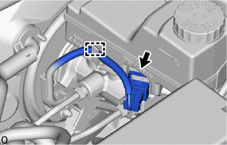
|
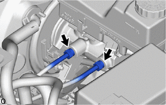
(b) Using a union nut wrench, disconnect the 2 brake lines from the brake master cylinder sub-assembly. NOTICE:
|
|
|
(c) Using a 13 mm deep socket wrench, remove the nut and separate the wire harness bracket. |
|
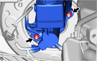
(d) Using a 13 mm deep socket wrench, remove the nut and brake master cylinder sub-assembly from the brake booster assembly.
NOTICE:
- The brake master cylinder sub-assembly requires careful handling. Do not drop or subject the brake master cylinder sub-assembly to any impact. Do not reuse a brake master cylinder sub-assembly that has been dropped.
- Do not hold the brake master cylinder sub-assembly by the master cylinder piston. Hold the brake master cylinder sub-assembly by its body or its brake master cylinder reservoir assembly when carrying it.
- Do not pull out the master cylinder piston.
- Do not strike or pinch the master cylinder piston, or cause any damage to the master cylinder piston by any other means.
- When installing the brake master cylinder sub-assembly to the brake booster assembly, or when removing the brake master cylinder sub-assembly from the brake booster assembly, make sure that the brake master cylinder sub-assembly is kept horizontal or with its tip facing downward (the master cylinder piston is facing upward) to prevent the master cylinder piston from falling out.
- Do not allow any foreign matter to contaminate the master cylinder piston. If any foreign matter gets on the master cylinder piston, remove it by using a piece of cloth and then apply an even layer of lithium soap base glycol grease around the circumference (sliding part) of the master cylinder piston.
- Do not use any other type of grease or fluid.
- Make sure to release vacuum from the brake booster assembly before removing the brake master cylinder sub-assembly from the brake booster assembly.
(e) Remove the brake master cylinder O-ring from the brake master cylinder sub-assembly.
 Components
COMPONENTS
ILLUSTRATION
*1
COWL BODY MOUNTING REINFORCEMENT LH
*2
COWL BODY MOUNTING REINFORCEMENT RH
*3
NO. 1 HEATER AIR DU ...
 Disassembly
DISASSEMBLY
PROCEDURE
1. REMOVE BRAKE MASTER CYLINDER RESERVOIR ASSEMBLY
(a) Mount the brake master cylinder sub-assembly in a vise.
NOTICE:
Place aluminum plates on the vise to prevent damage to ...
Other materials:
Toyota CH-R Service Manual > Audio And Visual System(for Radio And Display Type): Satellite Radio Broadcast cannot be Received
CAUTION / NOTICE / HINT
NOTICE:
Some satellite radio broadcasts require payment. A contract must be made between
a satellite radio company and the user. If the contract expires, it will not be
possible to listen to the broadcast.
WIRING DIAGRAM
for TMMT Made
for TMC Made
PROCEDURE
...
Toyota CH-R Service Manual > Smart Key System(for Entry Function): Diagnosis System
DIAGNOSIS SYSTEM
DESCRIPTION
(a) Smart key system (for Entry Function) data and Diagnostic Trouble Codes (DTCs)
can be read through the vehicle Data Link Connector 3 (DLC3). In some cases, a malfunction
may be occurring in the smart key system. When the system seems to be malfunctioning,
use ...
Toyota C-HR (AX20) 2023-2026 Owner's Manual
Toyota CH-R Owners Manual
- For safety and security
- Instrument cluster
- Operation of each component
- Driving
- Interior features
- Maintenance and care
- When trouble arises
- Vehicle specifications
- For owners
Toyota CH-R Service Manual
- Introduction
- Maintenance
- Audio / Video
- Cellular Communication
- Navigation / Multi Info Display
- Park Assist / Monitoring
- Brake (front)
- Brake (rear)
- Brake Control / Dynamic Control Systems
- Brake System (other)
- Parking Brake
- Axle And Differential
- Drive Shaft / Propeller Shaft
- K114 Cvt
- 3zr-fae Battery / Charging
- Networking
- Power Distribution
- Power Assist Systems
- Steering Column
- Steering Gear / Linkage
- Alignment / Handling Diagnosis
- Front Suspension
- Rear Suspension
- Tire / Wheel
- Tire Pressure Monitoring
- Door / Hatch
- Exterior Panels / Trim
- Horn
- Lighting (ext)
- Mirror (ext)
- Window / Glass
- Wiper / Washer
- Door Lock
- Heating / Air Conditioning
- Interior Panels / Trim
- Lighting (int)
- Meter / Gauge / Display
- Mirror (int)
- Power Outlets (int)
- Pre-collision
- Seat
- Seat Belt
- Supplemental Restraint Systems
- Theft Deterrent / Keyless Entry

0.0071