Toyota CH-R Service Manual: Inspection
INSPECTION
PROCEDURE
1. INSPECT SPIRAL CABLE SUB-ASSEMBLY
NOTICE:
- Do not remove the steering sensor from the spiral cable sub-assembly when inspecting the spiral cable sub-assembly.
- Remove the steering sensor from the spiral cable sub-assembly only when replacing the spiral cable sub-assembly.
(a) Visually check the spiral cable sub-assembly for defects.
(1) The defects are as follows:
- Scratches
- Small cracks
- Dents
- Chips
- Cracks or other damage to the connector
OK:
No defects are found.
If any of the defects is found, replace the spiral cable sub-assembly with a new one.
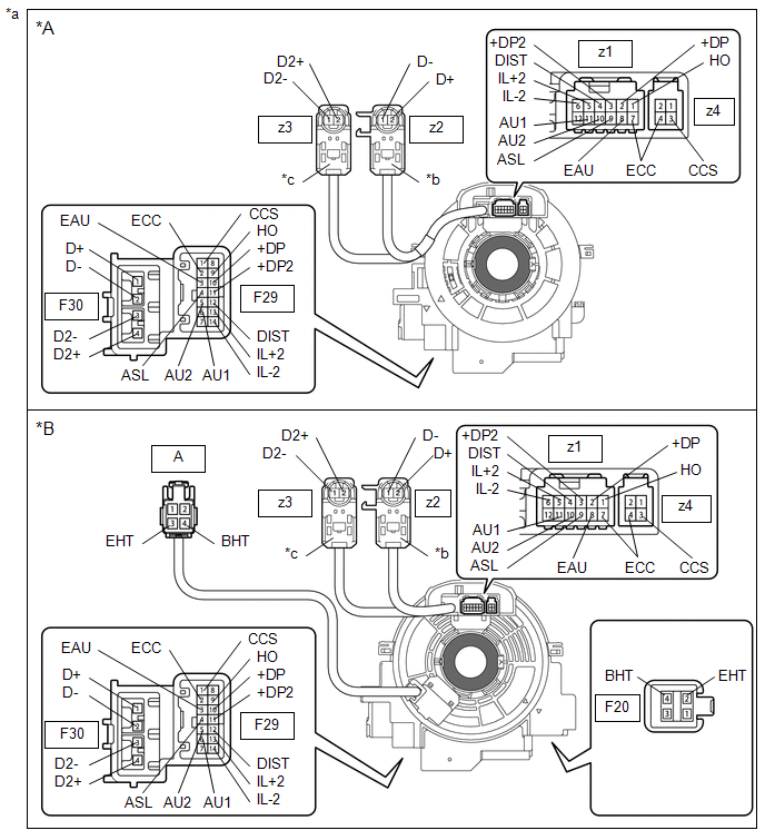
(b) Check the spiral cable sub-assembly.
|
*A |
w/o Steering Heater |
*B |
w/ Steering Heater |
|
*a |
Component without harness connected (Spiral Cable Sub-assembly) |
*b |
Color: Light Green |
|
*c |
Color: Black |
- |
- |
.png) |
Interlock |
- |
- |
NOTICE:
- When rotating the spiral cable sub-assembly, make sure to push on the interlock shown in the illustration to release the interlock mechanism.
- As the spiral cable sub-assembly may break, do not rotate the spiral cable sub-assembly more than the specified amount.
(1) Set the spiral cable sub-assembly to the center position.
- w/o Steering Heater:
Click here
.gif)
- w/ Steering Heater:
Click here
(2) Measure the resistance between each terminal of the spiral cable sub-assembly according to the value(s) in the table below.
Standard Resistance:
|
Tester Connection |
Condition |
Specified Condition |
|---|---|---|
|
F29-1 (CCS) - z4-3 (CCS) |
Always |
3 Ω or less |
|
F29-2 (ECC) - z1-7 (ECC) |
Always |
3 Ω or less |
|
F29-2 (ECC) - z4-4 (ECC) |
Always |
3 Ω or less |
|
F29-3 (EAU) - z1-8 (EAU) |
Always |
3 Ω or less |
|
F29-5 (AU2) - z1-10 (AU2) |
Always |
3 Ω or less |
|
F29-6 (AU1) - z1-11 (AU1) |
Always |
3 Ω or less |
|
F29-9 (HO) - z1-1 (HO) |
Always |
3 Ω or less |
|
F29-10 (+DP) - z1-2 (+DP) |
Always |
3 Ω or less |
|
F29-11 (+DP2) - z1-3 (+DP2) |
Always |
3 Ω or less |
|
F29-12 (DIST) - z1-4 (DIST) |
Always |
3 Ω or less |
|
F29-13 (IL+2) - z1-5 (IL+2) |
Always |
3 Ω or less |
|
F29-14 (IL-2) - z1-6 (IL-2) |
Always |
3 Ω or less |
|
F20-2 (EHT) - z6-3 (EHT)*1 |
Always |
3 Ω or less |
|
F20-4 (BHT) - z6-4 (BHT)*1 |
Always |
3 Ω or less |
|
F30-1 (D+) - z2-2 (D+) |
Always |
Below 1 Ω |
|
F30-2 (D-) - z2-1 (D-) |
Always |
Below 1 Ω |
|
F30-3 (D2-) - z15-1 (D2-)*2 |
Always |
Below 1 Ω |
|
F30-4 (D2+) - z15-2 (D2+)*2 |
Always |
Below 1 Ω |
- *1: w/ Steering Heater
- *2: for Dual Type
(3) After setting the spiral cable sub-assembly to the center position, rotate the spiral cable sub-assembly 2.5 times clockwise, and measure the resistance according to the value(s) in the table below. Then rotate the spiral cable sub-assembly 5 times counterclockwise, and measure the resistance according to the value(s) in the table below.
Standard Resistance:
|
Tester Connection |
Condition |
Specified Condition |
|---|---|---|
|
F29-1 (CCS) - z4-3 (CCS) |
Always |
3 Ω or less |
|
F29-2 (ECC) - z1-7 (ECC) |
Always |
3 Ω or less |
|
F29-2 (ECC) - z4-4 (ECC) |
Always |
3 Ω or less |
|
F29-3 (EAU) - z1-8 (EAU) |
Always |
3 Ω or less |
|
F29-5 (AU2) - z1-10 (AU2) |
Always |
3 Ω or less |
|
F29-6 (AU1) - z1-11 (AU1) |
Always |
3 Ω or less |
|
F29-9 (HO) - z1-1 (HO) |
Always |
3 Ω or less |
|
F29-10 (+DP) - z1-2 (+DP) |
Always |
3 Ω or less |
|
F29-11 (+DP2) - z1-3 (+DP2) |
Always |
3 Ω or less |
|
F29-12 (DIST) - z1-4 (DIST) |
Always |
3 Ω or less |
|
F29-13 (IL+2) - z1-5 (IL+2) |
Always |
3 Ω or less |
|
F29-14 (IL-2) - z1-6 (IL-2) |
Always |
3 Ω or less |
|
F20-2 (EHT) - A-3 (EHT)*1 |
Always |
3 Ω or less |
|
F20-4 (BHT) - A-4 (BHT)*1 |
Always |
3 Ω or less |
|
F30-1 (D+) - z2-2 (D+) |
Always |
Below 1 Ω |
|
F30-2 (D-) - z2-1 (D-) |
Always |
Below 1 Ω |
|
F30-3 (D2-) - z15-1 (D2-)*2 |
Always |
Below 1 Ω |
|
F30-4 (D2+) - z15-2 (D2+)*2 |
Always |
Below 1 Ω |
- *1: w/ Steering Heater
- *2: for Dual Type
(4) After setting the spiral cable sub-assembly to the center position, rotate the spiral cable sub-assembly 2.5 times clockwise. Then while rotating the spiral cable sub-assembly 5 times counterclockwise, measure the resistance according to the value(s) in the table below.
Standard Resistance:
|
Tester Connection |
Condition |
Specified Condition |
|---|---|---|
|
F29-1 (CCS) - z4-3 (CCS) |
Always |
3 Ω or less |
|
F29-2 (ECC) - z1-7 (ECC) |
Always |
3 Ω or less |
|
F29-2 (ECC) - z4-4 (ECC) |
Always |
3 Ω or less |
|
F29-3 (EAU) - z1-8 (EAU) |
Always |
3 Ω or less |
|
F29-5 (AU2) - z1-10 (AU2) |
Always |
3 Ω or less |
|
F29-6 (AU1) - z1-11 (AU1) |
Always |
3 Ω or less |
|
F29-9 (HO) - z1-1 (HO) |
Always |
3 Ω or less |
|
F29-10 (+DP) - z1-2 (+DP) |
Always |
3 Ω or less |
|
F29-11 (+DP2) - z1-3 (+DP2) |
Always |
3 Ω or less |
|
F29-12 (DIST) - z1-4 (DIST) |
Always |
3 Ω or less |
|
F29-13 (IL+2) - z1-5 (IL+2) |
Always |
3 Ω or less |
|
F29-14 (IL-2) - z1-6 (IL-2) |
Always |
3 Ω or less |
|
F20-2 (EHT) - A-3 (EHT)*1 |
Always |
3 Ω or less |
|
F20-4 (BHT) - A-4 (BHT)*1 |
Always |
3 Ω or less |
|
F30-1 (D+) - z2-2 (D+) |
Always |
Below 1 Ω |
|
F30-2 (D-) - z2-1 (D-) |
Always |
Below 1 Ω |
|
F30-3 (D2-) - z15-1 (D2-)*2 |
Always |
Below 1 Ω |
|
F30-4 (D2+) - z15-2 (D2+)*2 |
Always |
Below 1 Ω |
- *1: w/ Steering Heater
- *2: for Dual Type
If the result is not as specified, replace the spiral cable sub-assembly.
 Components
COMPONENTS
ILLUSTRATION
*1
LOWER STEERING COLUMN COVER SUB-ASSEMBLY
*2
SPIRAL CABLE WITH SENSOR SUB-ASSEMBLY
*3
UPPER STEERI ...
 Removal
REMOVAL
CAUTION / NOTICE / HINT
The necessary procedures (adjustment, calibration, initialization, or registration)
that must be performed after parts are removed, installed, or replaced during th ...
Other materials:
Toyota CH-R Service Manual > Rear View Monitor System: System Description
SYSTEM DESCRIPTION
GENERAL
(a) This system has a rear television camera assembly mounted on the back door
to assist the driver in parking the vehicle by displaying an image of the area behind
the vehicle. The system displays the image on the multi-display.
(b) This system consists of the foll ...
Toyota CH-R Service Manual > Lighting System: Light Sensor Circuit Malfunction (B1244)
DESCRIPTION
The automatic light control sensor detects ambient light. The sensor creates
an electrical signal based on the amount of light detected, and sends the signal
to the main body ECU (multiplex network body ECU). The main body ECU (multiplex
network body ECU) turns on or off the headl ...
Toyota C-HR (AX20) 2023-2026 Owner's Manual
Toyota CH-R Owners Manual
- For safety and security
- Instrument cluster
- Operation of each component
- Driving
- Interior features
- Maintenance and care
- When trouble arises
- Vehicle specifications
- For owners
Toyota CH-R Service Manual
- Introduction
- Maintenance
- Audio / Video
- Cellular Communication
- Navigation / Multi Info Display
- Park Assist / Monitoring
- Brake (front)
- Brake (rear)
- Brake Control / Dynamic Control Systems
- Brake System (other)
- Parking Brake
- Axle And Differential
- Drive Shaft / Propeller Shaft
- K114 Cvt
- 3zr-fae Battery / Charging
- Networking
- Power Distribution
- Power Assist Systems
- Steering Column
- Steering Gear / Linkage
- Alignment / Handling Diagnosis
- Front Suspension
- Rear Suspension
- Tire / Wheel
- Tire Pressure Monitoring
- Door / Hatch
- Exterior Panels / Trim
- Horn
- Lighting (ext)
- Mirror (ext)
- Window / Glass
- Wiper / Washer
- Door Lock
- Heating / Air Conditioning
- Interior Panels / Trim
- Lighting (int)
- Meter / Gauge / Display
- Mirror (int)
- Power Outlets (int)
- Pre-collision
- Seat
- Seat Belt
- Supplemental Restraint Systems
- Theft Deterrent / Keyless Entry

0.0083